
Circumferential Linear Parking Hoist

A linear and circular technology, applied in the field of circular linear parking lifting devices, to achieve the effects of compact structure, full use of land area, increased reliability and equipment life

Inactive Publication Date: 2011-11-30
刘奇鲜
View PDF1 Cites 0 Cited by
  • Summary
  • Abstract
  • Description
  • Claims
  • Application Information

AI Technical Summary

Problems solved by technology

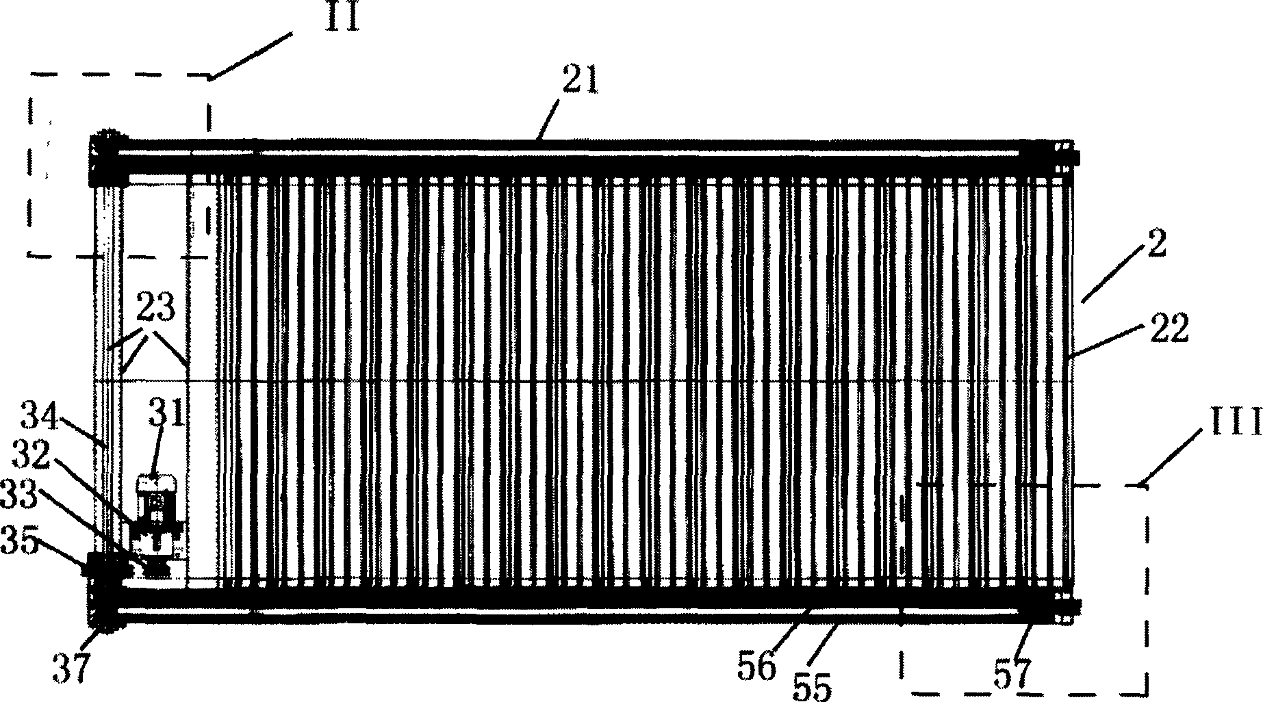
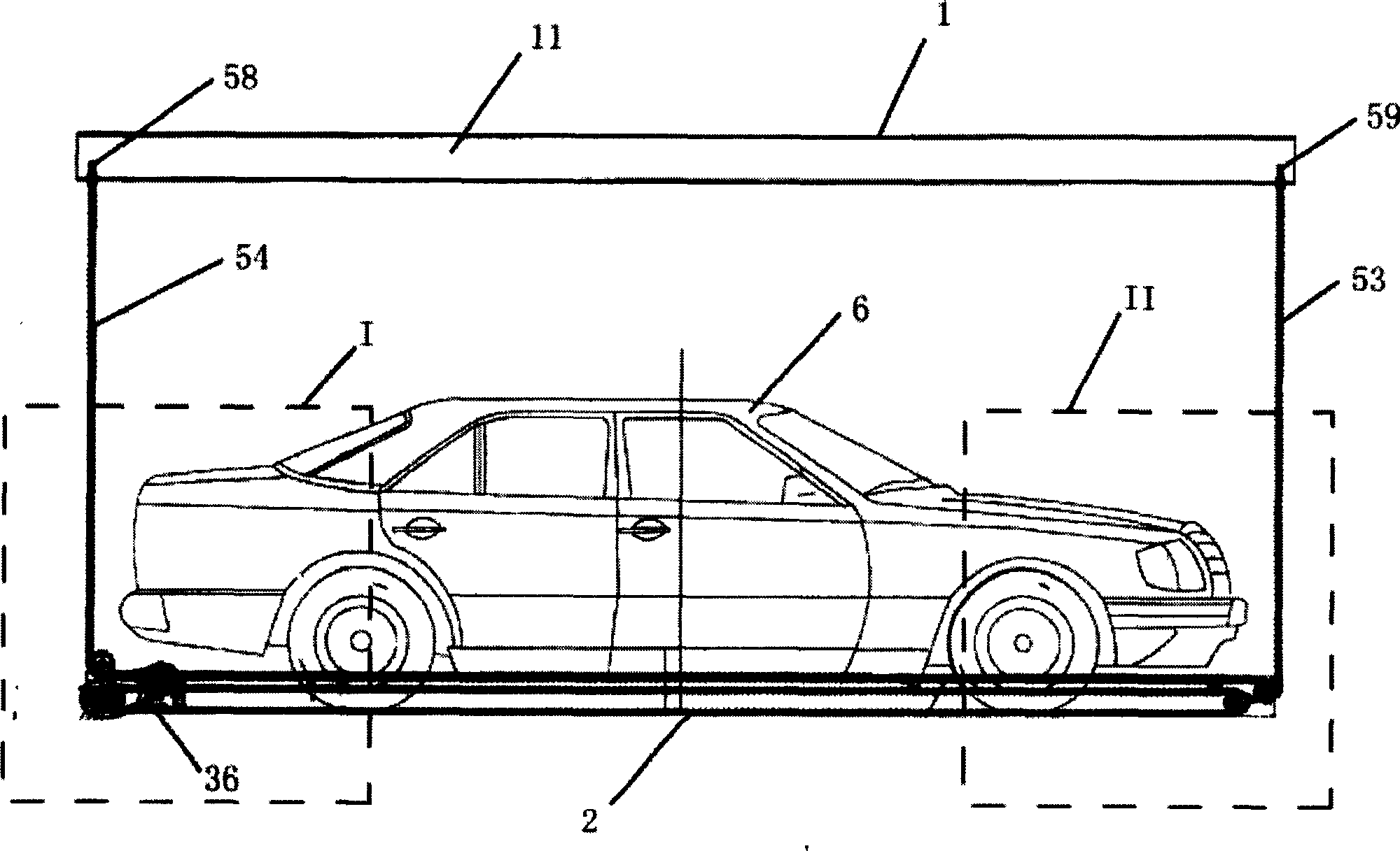
[0018] The technical problem to be solved by the present invention is to provide a circular linear parking lifting device. The lifting device places the lifting drive device on the vehicle loading plate and uses a chain to transmit power, which solves many shortcomings of the existing parking lifting device.

Method used


Image

  • Circumferential Linear Parking Hoist
  • Circumferential Linear Parking Hoist
  • Circumferential Linear Parking Hoist

Examples


Embodiment 1

[0059] Each group of lifting mechanism includes synchronous sprocket I 41, II42, rear guide sprocket I 43, II44, rear steering sprocket, front steering sprocket I 46, II47, front guide sprocket I 48, II49, front idler sprocket I 51 , II52, front and rear suspension chains 53,54, epicyclic chain I 55, II 56, four and a chain joint 57. The synchronous sprocket I 41, II42 and the rear guide sprocket I 43, II44 are keyed and fixed on the shaft end of the synchronous main shaft 34, and the rear guide sprocket I 43, II44 is between the synchronous sprocket I 41, II42. Rear steering sprocket shaft is located on the vehicle platform 2 and has a synchronous main shaft 34 one end, and the position is higher than synchronous sprocket I 41, II 42 (referring to Figure 11 ).

[0060] Front steering sprocket I 46, II47, front guide sprocket I 48, II49, front idler sprocket I 51, II52 shafts are located at the other end of the vehicle platform 2, and the position of front steering sprocket ...

Embodiment 2

[0069] The utility model can also have the following changes: the rear guide wire rope wheels I and II replace the rear guide sprockets I 43 and II44, the rear steering wire rope wheels replace the rear steering sprockets, and the front steering wire rope wheels I and II replace the front steering sprocket I 46, II 47, the leading wire rope I, II replace the leading sprocket I 48, II 49, the front and rear suspension wire ropes replace the front and rear suspension chains 53, 54, four and one wire rope joints replace four and one chain joints 57 and the rest of the structure and Working principle is the same as embodiment 1.


PUM


Abstract

A circumferential linear parking lifting device, including a main body frame and a vehicle-carrying platform accommodated in the main frame, it also includes a lifting motor arranged on the rear side of the vehicle-carrying platform and a lifting motor gearbox driven by the lifting motor; The synchronous main shaft at one end of the vehicle-carrying platform, the gear box of the lifting motor drives the synchronous main shaft to rotate through the chain transmission mechanism; a group of lifting mechanisms are respectively arranged on both sides of the vehicle-carrying platform, and the lifting mechanisms drive the vehicle-carrying platform to lift. The hoisting motor drives the hoisting motor gearbox to work, the hoisting motor gearbox drives the synchronous main shaft to rotate, and the synchronous main shaft drives two groups of chain hoisting mechanisms to realize the lifting of the vehicle platform.

Description

technical field [0001] The invention relates to a parking hoisting device, in particular to a circular linear parking hoisting device with a lower lifting power. Background technique [0002] Conventional three-dimensional parking device, the elevating drive mechanism of its car-carrying plate is all arranged on the steel structure that is parked and loaded. This arrangement mainly has the following defects: [0003] 1. The parking device has large vertical and horizontal dimensions in the direction of parking the vehicle, the external dimension of the parking system is large, and the utilization rate of the parking space is low. [0004] 2. After the lifting drive mechanism is placed on the top, the parking position is not accurate due to the different models of vehicles parked on the vehicle-carrying plate, the size of the front and rear overhangs is different, and the lifting process of the vehicle-carrying plate will interfere with the size of the parked vehicle and the...

Claims


Application Information

Patent Timeline
Patent Type & Authority Patents(China)
IPC IPC(8): E04H6/18E04H6/06
Inventor 刘奇鲜
Owner 刘奇鲜
Learn More