

Indicating instrument full-automatic test method based on computer visual sense technology
A technology of computer vision and indicating instruments, applied in the direction of instruments, measuring devices, measuring electrical variables, etc., can solve the problems of recognition errors, false detections, and restrictions on the application of automatic verification, so as to improve accuracy and avoid recognition errors.
- Summary
- Abstract
- Description
- Claims
- Application Information
AI Technical Summary
Problems solved by technology
Method used
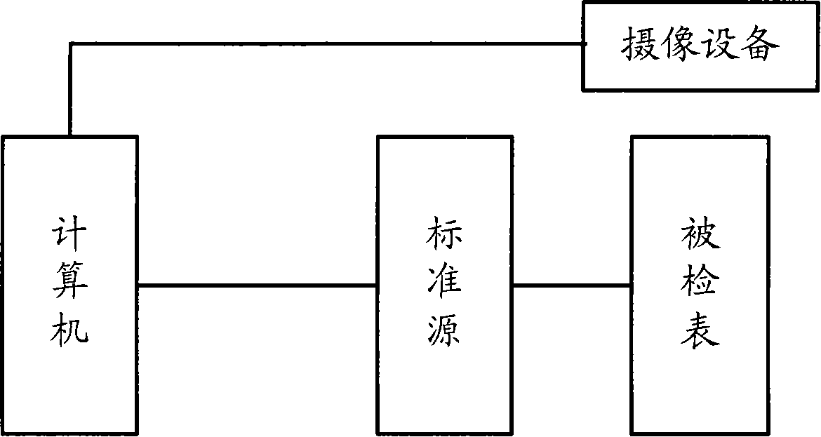
Image

Examples
Embodiment 1
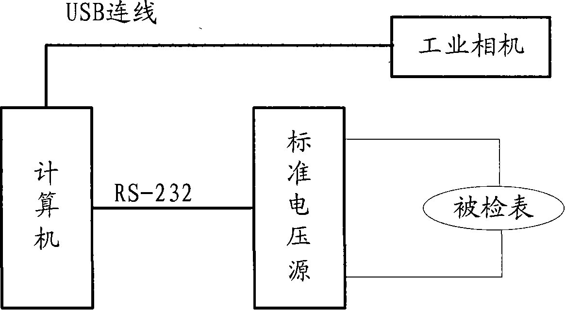
[0055] Take the full-automatic verification of voltmeter as an example below to illustrate the method set forth in the present invention, as image 3 Shown:
[0056] The first step is to input the information of the meter to be inspected. Generally, the information to be input includes: meter type (voltmeter), measuring range (300V), and uniform inspection points (3);
[0057] The second step is to input image feature information, including: indicator movement mode (circle), indicator circle center position (bottom right), scale angle range (0-90);
[0058] In the third step, the content of the viewfinder is displayed on the computer, and the range of the instrument is delineated with the mouse. Generally, the range of the dial can be taken, and the subsequent image recognition software only needs to process and recognize the images within the range.
[0059] In the fourth step, the computer displays the recognized image to the user for checking and modification by the user; ...
PUM
 Abstract
Description
Claims
Application Information