Optical module and its alignment and assembly method

A technology of optical modules and assembly methods, applied in optics, optical components, installation, etc., can solve problems such as poor alignment accuracy and inability to improve the resolution of optical modules 1, and achieve the effect of improving alignment accuracy

Inactive Publication Date: 2008-08-13
UNIVERSAL SCIENTIFIC INDUSTRIAL (SHANGHAI) CO LTD +1
View PDF1 Cites 2 Cited by
  • Summary
  • Abstract
  • Description
  • Claims
  • Application Information

AI Technical Summary

Problems solved by technology

[0005] However, considering the cost, the lens unit 13 of the optical module 1 is usually manually placed in the groove 113 for assembly, ignoring the light of the lens unit 13 itself. The error of the axial length is about +/-400 microns, and the relative position between the lens unit 13 and the ph

Method used


Image

  • Optical module and its alignment and assembly method
  • Optical module and its alignment and assembly method
  • Optical module and its alignment and assembly method

Examples


Embodiment Construction

[0023] The present invention will be described in detail below in conjunction with the accompanying drawings and embodiments.

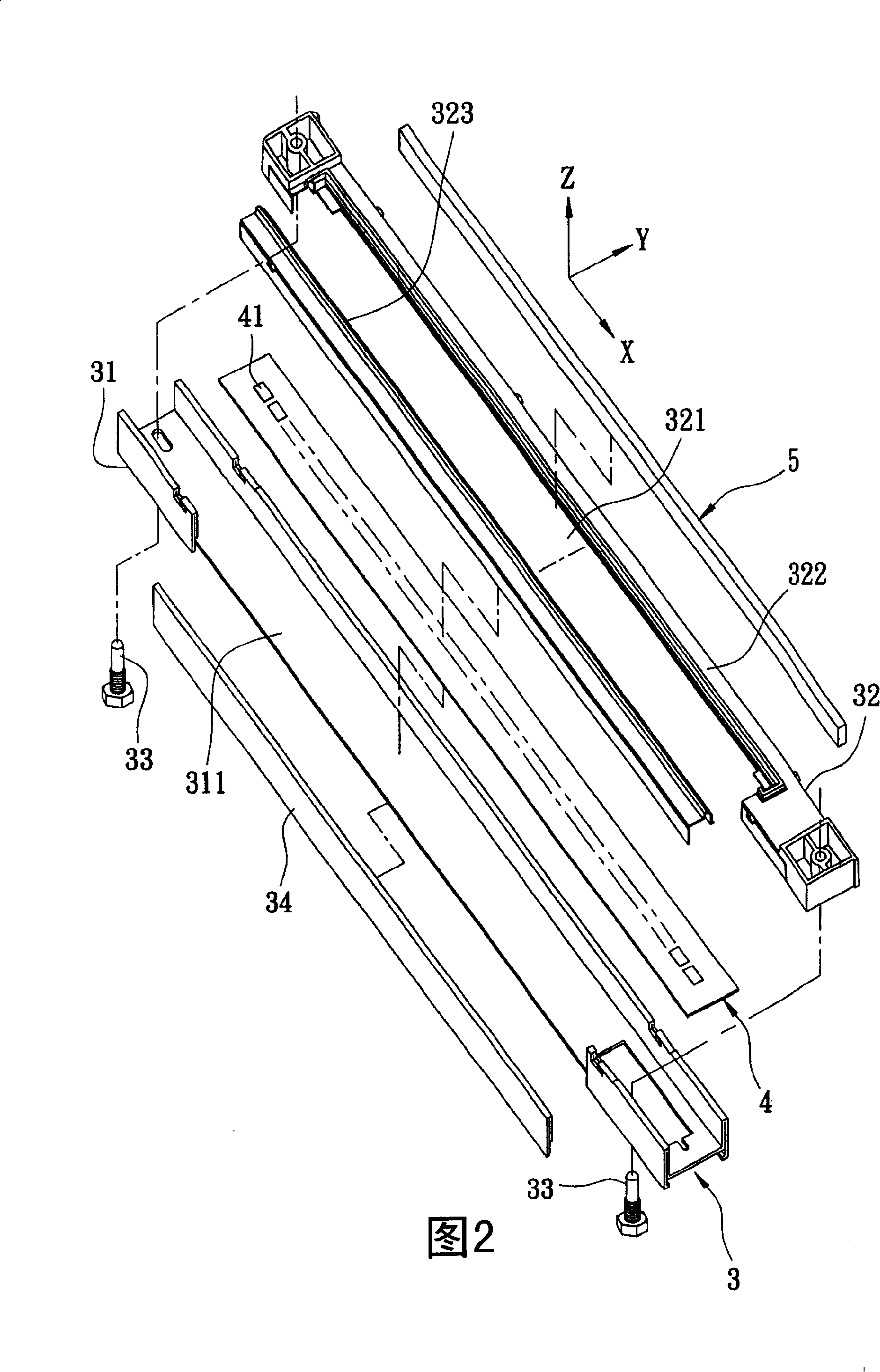
[0024] Referring to FIG. 2 and FIG. 3 , the preferred embodiment of the optical module of the present invention is an optical system applied to a light input device, and a light source is projected against a piece of glass 9 . The glass 9 has a top surface 91 capable of holding an object. The optical module includes: a housing unit 3 , a photosensitive unit 4 and a lens unit 5 .

[0025] The shell base unit 3 extends along the X-axis direction, and has a roughly U-shaped shell 31, a base 32 mounted on the shell 31, and two through the shell 31 and the base 32. Two positioning pieces 33 and a cover plate 34 at the end. The housing 31 has an opening 311 formed on one side and extending along the X-axis direction. The base 32 has a first mating part 322 and a second mating part 323 mated with each other and defining a slot 321. The second mating part ...


PUM


Abstract

The present invention provides an optical module and its aiming, assembling method, the optical module includes a case unit, a sensitive unit fixed in the case unit, and a lens unit which the focusing source is on the sensitive unit. The case unit has an opening formed on one side. The lens unit is placed on the case and displayed in the opening relative to the sensitive unit frame. In addition, when assembling, the lens unit is inserted in the case unit by the opening, when aiming, only retrieving the center position of the lens coinciding to the center position of the sensitization unit to the object position after deducting the repairing optical length, can complete optical alignment, and greatly echance accuracy and conveniences when assembled.

Description

technical field [0001] The present invention relates to an optical module, in particular to an optical module capable of sensing images and an alignment and assembly method thereof. Background technique [0002] refer to figure 1 , taking the optical module 1 of a general optical image input device such as a scanner as an example, it mainly includes a housing unit 11 , a photosensitive unit 12 , a lens unit 13 and a light emitting unit 14 . The shell-base unit 11 has a shell 111 and a base 112 matched with each other, and a groove 113 formed in the shell 111 . The photosensitive unit 12 has a plurality of photosensitive elements 121 arranged in a straight line on the base 112 , and the photosensitive elements 121 are a CMOS (Complementary Metal Oxide Semiconductor) image sensor scanner (ImageSensor Scanner). The lens unit 13 is embedded in the groove 113 of the casing 111 relative to the photosensitive unit 12 . The light emitting unit 14 is disposed on the housing 111 re...

Claims


Application Information

Patent Timeline
IPC IPC(8): H04N1/028H04N1/024G02B7/02
Inventor 吴明哲
Owner UNIVERSAL SCIENTIFIC INDUSTRIAL (SHANGHAI) CO LTD
Why Eureka
Try Eureka