Sensor-equipped bearing for wheel

A sensor and deformation sensor technology, which is used in the direction of rotating bearings, bearings, axles, etc., to achieve the effects of high reliability, good radial deformation, and easy installation

Inactive Publication Date: 2008-08-13
NTN CORP
View PDF1 Cites 6 Cited by
  • Summary
  • Abstract
  • Description
  • Claims
  • Application Information

AI Technical Summary

Problems solved by technology

However, the problem of detecting the deformation of the outer ring with good sensitivity has not yet been solved.

Method used


Image

  • Sensor-equipped bearing for wheel
  • Sensor-equipped bearing for wheel
  • Sensor-equipped bearing for wheel

Examples


Embodiment Construction

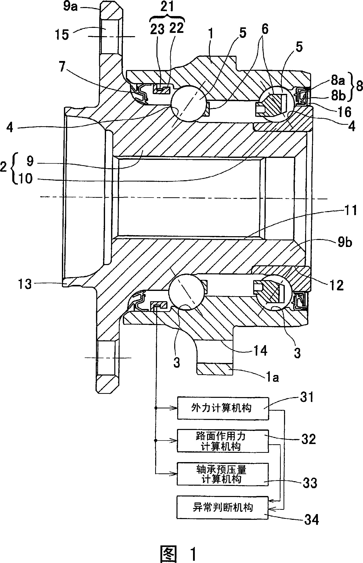
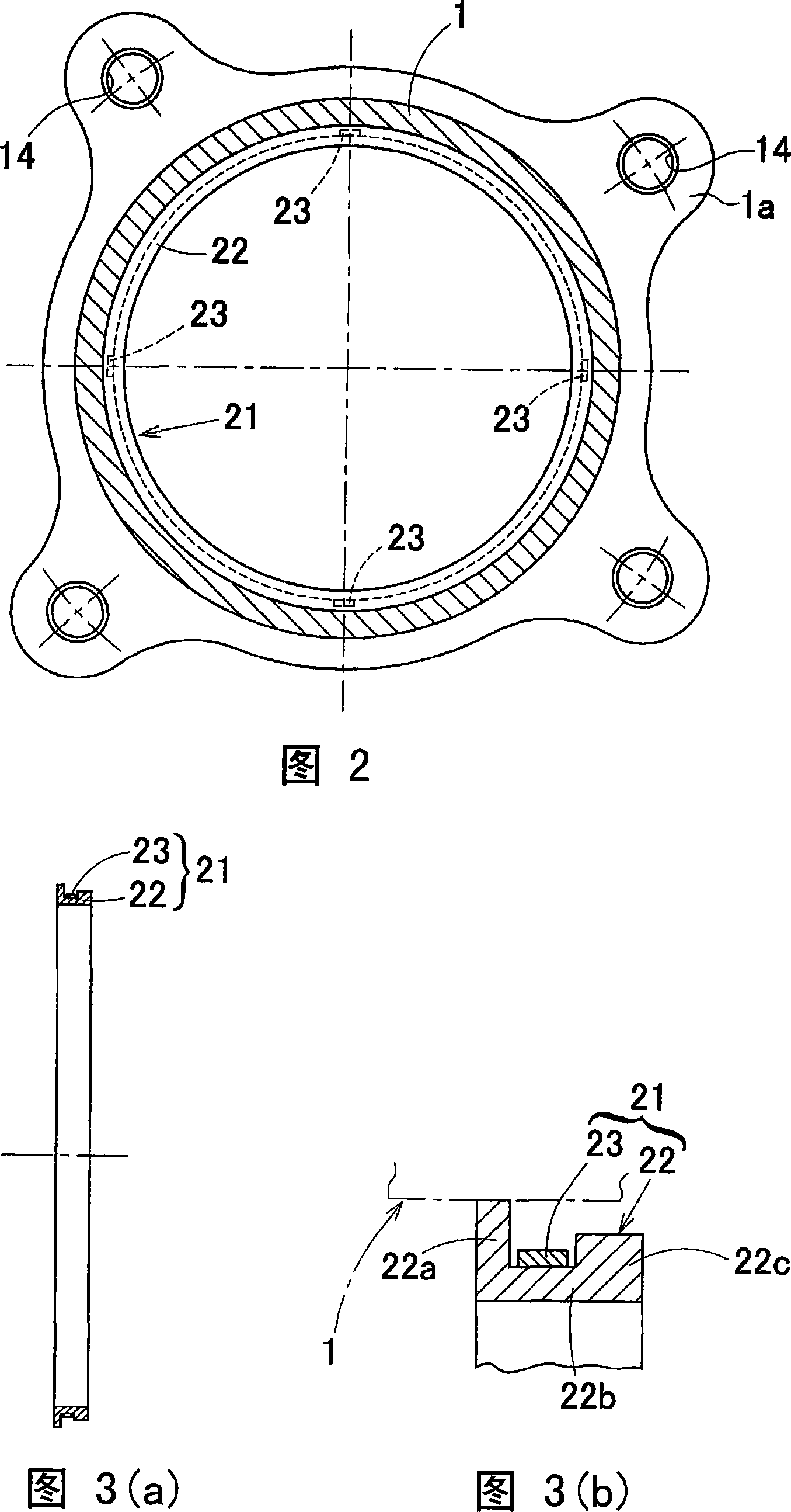
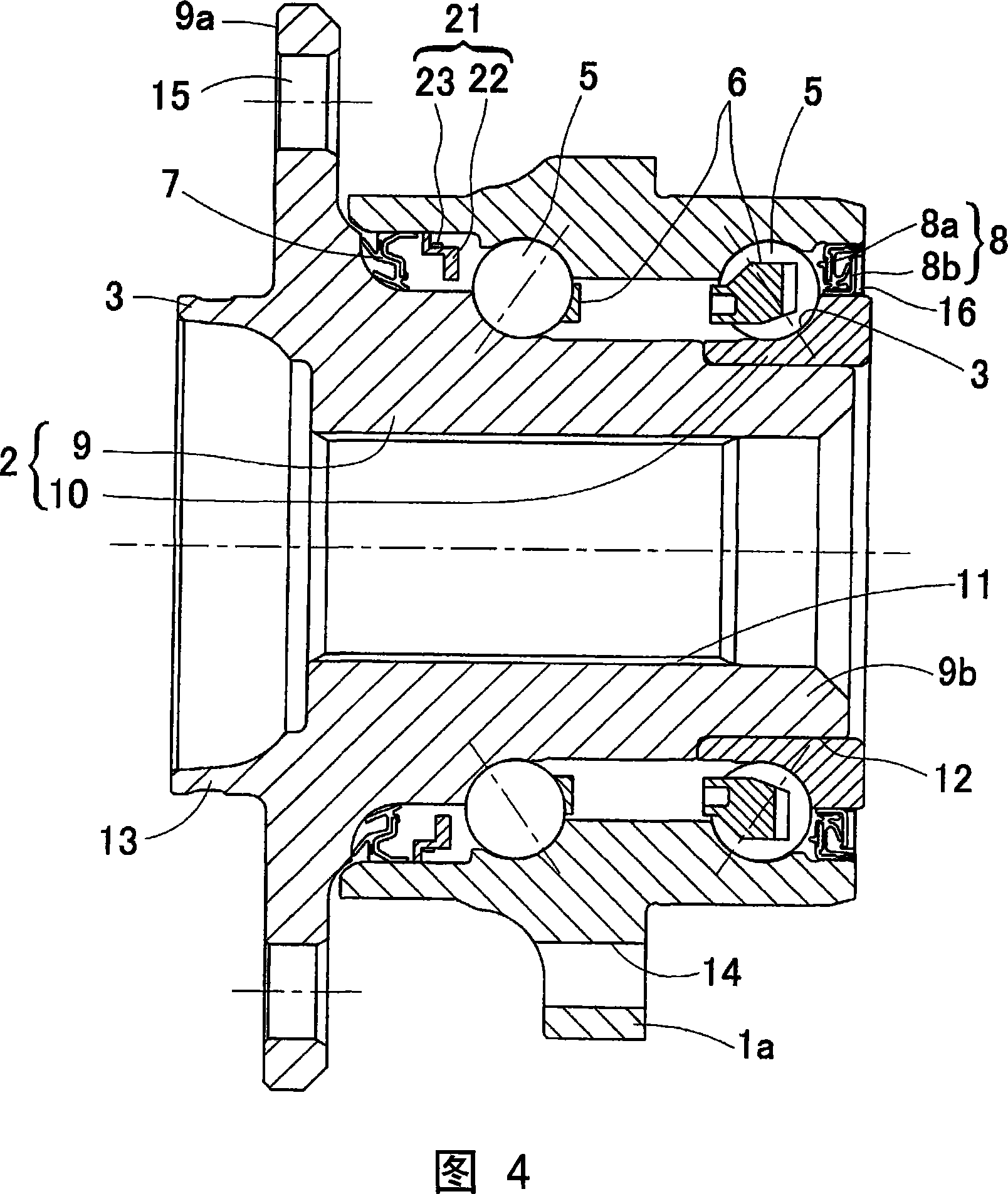
[0114] A first embodiment of the present invention will be described with reference to FIGS. 1 to 3 . This embodiment is a third-generation inner ring rotary type, which is suitable for a wheel bearing for supporting a driving wheel. In addition, in this specification, when mounted on a vehicle, the side closer to the outer side in the vehicle width direction of the vehicle is referred to as the outer side, and the side closer to the middle of the vehicle is referred to as the inner side.

[0115] The wheel bearing with sensors is composed of an outer part 1, an inner part 2 and multiple rows of rolling elements 5. In the outer part 1, multiple rows of rolling surfaces 3 are formed on the inner periphery. The inner part 2 A rolling surface 4 facing each rolling surface 3 is formed, and the plurality of rows of rolling elements 5 are interposed between the rolling surfaces 3 , 4 of the outer member 1 and the inner member 2 . The wheel bearing is a multi-row angular contact bal...


PUM


Abstract

A bearing for a vehicle, enabling a load sensor to be compactly installed on the vehicle and capable of detecting a load on a wheel with good sensitivity. A ring member (22) is attached to a circumferential surface or an end surface of a stationary member out of an outer member (1) and an inner member (2). The ring member (22) has at an intermediate section of it a first contactless ring section (22b (22f, 22i)) not in contact with the stationary member, has at one end a first contact ring section (22a (22g)) in contact with the stationary member, and has at the other end the following (A) or (B): (A) a second contactless ring section (22c(22d)) having greater wall thickness than the first contactless ring section (22b); (B) a second contact ring section (22e, (22h)) in contact with the stationary member. In (A), a sensor (23) for measuring strain of the ring member (22) is installed on the first contactless ring section (22b), and in (B), the sensor (23) is installed on the first contactless ring section (22f) or first contact ring section (22g) having the smallest wall thickness.

Description

technical field [0001] The present invention relates to a sensor-equipped bearing for a wheel having a built-in load sensor for detecting a load acting on a bearing portion of a wheel. Background technique [0002] In the past, for safe running of automobiles, sensors for detecting the rotational speed of each wheel were installed on wheel bearings. In the past, the driving safety assurance measures of ordinary cars were carried out by detecting the rotation speed of the wheels of each part. However, it is not enough to rely on the rotation speed of the wheels alone. It is required to use other sensor signals for further safety control. . [0003] Therefore, it is also considered to achieve attitude control based on the load acting on each wheel when the vehicle is running. For example, when turning, a large load acts on the outer wheel. In addition, when driving on a left-right inclined surface, on one wheel, when braking, the load is shifted to the front wheel, etc., act...

Claims


Application Information

Patent Timeline
Patent Type & Authority Applications(China)
IPC IPC(8): G01L5/00B60B35/18F16C19/18F16C41/00
Inventor 尾崎孝美石河智海西川健太郎
Owner NTN CORP
Why Eureka
Try Eureka