Power-driven system of aerial vehicle

A power-driven, aircraft technology, applied in the direction of aircraft, motor vehicles, aircraft parts, etc., can solve the problems that hinder the development and promotion of aircraft, heavy weight, increase in aircraft volume and weight, etc. The effect of efficiency, excellent controllability

Inactive Publication Date: 2008-08-20
周公平
View PDF0 Cites 43 Cited by
  • Summary
  • Abstract
  • Description
  • Claims
  • Application Information

AI Technical Summary

Problems solved by technology

On the one hand, this not only increases the volume and weight of the aircraft, but also causes the complexity of the design and control of the aircraft, making it difficult to realize the miniaturization and simplification of the aircraft structure, and the cost of the aircraft cannot be reduced, which hinders the development of the aircraft to a certain extent. Aircraft development and promotion
Even though there is already a coaxial twin-rotor helicopter that balances the reverse torsional moment, the coaxial system still uses a mechanical transmission control link to balance the reverse torque of the aircraft fuselage, which still makes the aircraft structure complex and heavy

Method used


Image

  • Power-driven system of aerial vehicle
  • Power-driven system of aerial vehicle

Examples


Embodiment approach 1

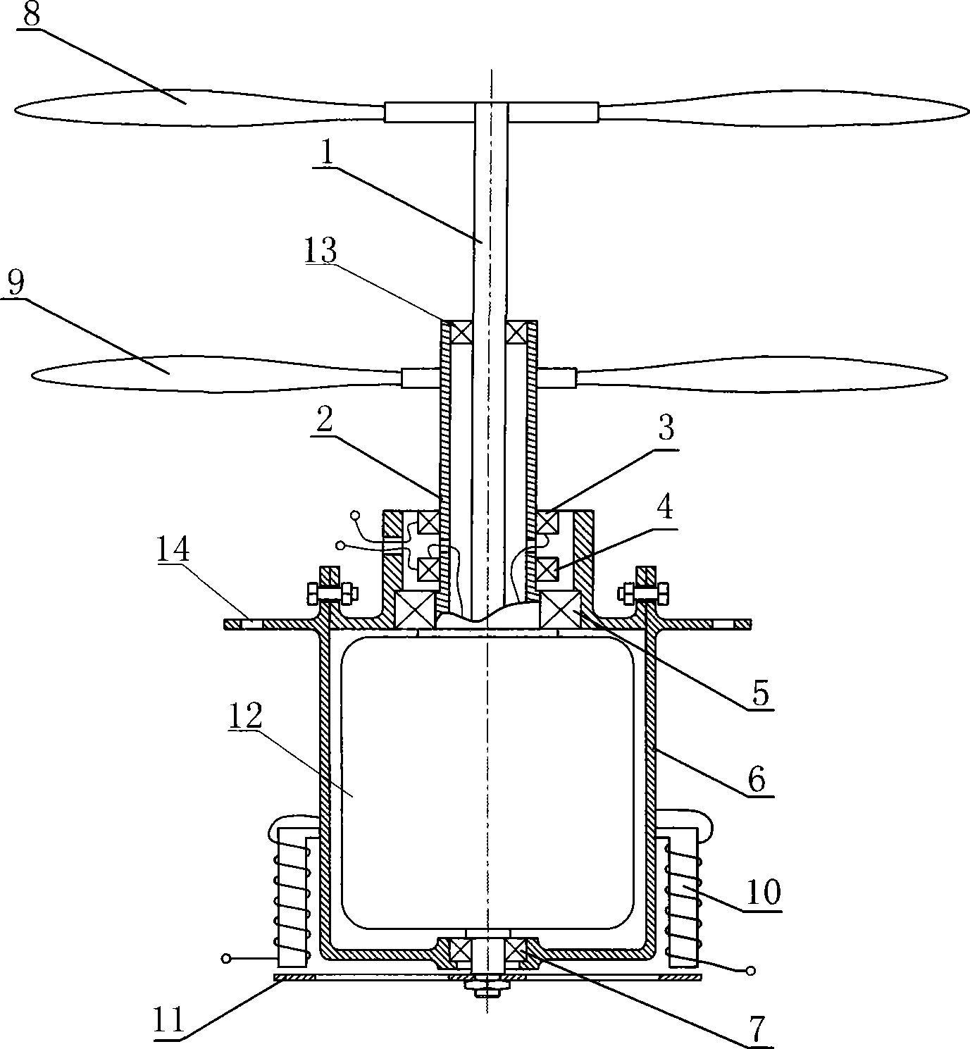
[0023] Embodiment 1 such as figure 1 As shown, in the power drive system of the aircraft, a storage battery is used as the power supply, and the motor is a special inner rotor brushed motor 12. The motor is vertically arranged in a bearing seat 6 through a bearing, and the stator 2 and the rotor 1 of the motor are all facing upwards. The propellers 9 and 8 are respectively installed in the direction of extension, the upper end of the stator and the rotor are installed coaxially with the propeller, and a turntable 11 is fixed after the lower end of the rotor 1 protrudes from the bearing seat. . One end of the motor is provided with a rotor bearing 7, and the other end of the motor is provided with a stator bearing 5. The propeller installed at one end of the rotor and the propeller installed on the stator are mutually rotating propellers, and the rotor bearing 7 and the stator bearing 5 are fixed on the bearing seat. ends. The bearing seat is provided with a fixed mounting ho...

Embodiment approach 2

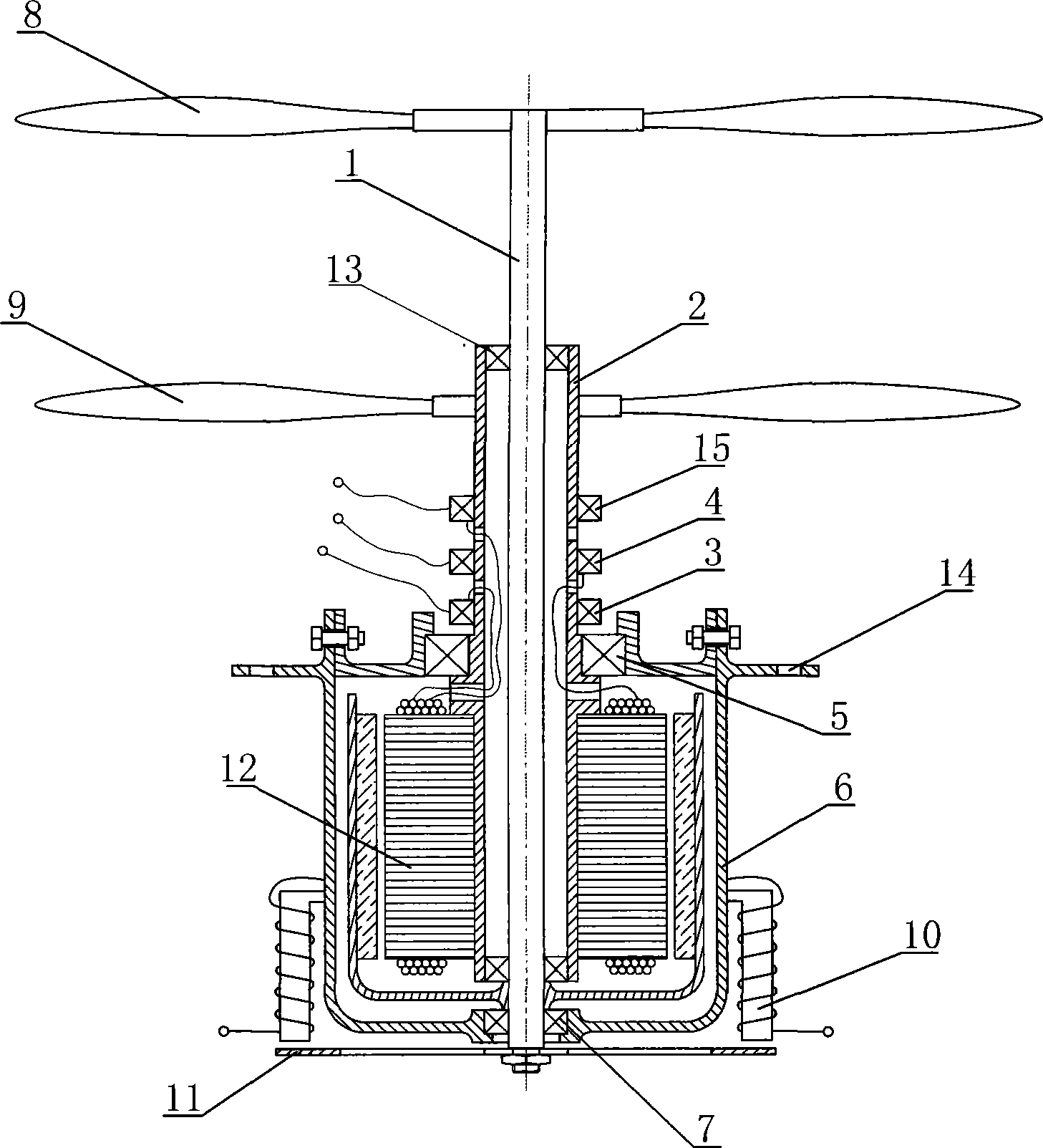
[0024] Embodiment 2 such as figure 2 As shown, in the power drive system of the aircraft, a storage battery is used as a power supply, and the motor is a special-made outer rotor brushless motor 12, and the outer rotor of the motor is a "mountain" font structure. The motor is vertically arranged in a bearing seat 6 through bearings, the stator 2 and rotor 1 of the motor extend upwards and are respectively installed with propellers 9 and 8, the upper end of the stator and the rotor are coaxially mounted on the propeller, and the lower end of the rotor 1 protrudes A rotating disk 11 is fixed behind the bearing seat, and an electromagnet 10 with a magnetic pole position close to the rotating disk is fixedly arranged outside the bearing seat. One end of the motor is provided with a rotor bearing 7, and the other end of the motor is provided with a stator bearing 5, and the propellers 9 and 8 are mutually rotating propellers, and the rotor bearing 7 and the stator bearing 5 are fi...


PUM


Abstract

The invention relates to a power driven system of the aircraft, which is characterized in that the power driven system comprises a power supply, a motor and a bearing support. The motor is vertically arranged in the bearing support by a bearing. Both the stator and the rotor of the motor are extending upwards and are respectively provided with propellers. The upper ends of the stator and the rotor where the propellers are arranged are coaxially sleeved, and the lower end of the rotor is fixed with a rotary disc after stretching out of the bearing support, an electromagnet with the magnetic pole part near the rotary disc is fixed-arranged outside the bearing support. When the motor is electrified, both the rotor and the stator drive the propellers to rotate to acquire power at the same time, and the power is transmitted to the frame by the bearing support to drive the aircraft to rise or advance. Meanwhile the electromagnetic moment between the electromagnet and the rotary disc is used to counteract the friction torque, and control the size of the electromagnetic moment to achieve the turning of the aircraft. The power driven system has the advantages of solving the problem of anti-torque of the propeller, satisfying the design requirements of miniature, simplification and lightness of the aircraft, and being beneficial to the popularization and manufacturing of the aircraft.

Description

technical field [0001] The invention belongs to the power drive system of aviation flight equipment, in particular to a torque-free power drive system suitable for various aviation aircraft driven by propellers. Background technique [0002] Existing helicopters, fixed-wing aircraft, etc. are all driven by propellers. This type of aviation aircraft is driven by an indirect reaction engine. The work done by the air accelerates the air backwards or downwards. At this time, the reaction force of the air on the propeller is used to propel the aircraft. Such engines include piston engines, turboprop engines, turboshaft engines, turboprop fan engines, and the like. The turbofan engine has both direct reaction force and indirect reaction force, but it is often classified as a direct reaction force engine, so it is also called a turbofan jet engine. [0003] No matter what kind of engine is used, the existing engine all adopts a drive shaft connected to the propeller as the power ...

Claims


Application Information

Patent Timeline
Patent Type & Authority Applications(China)
IPC IPC(8): B64C11/48B64C27/10B64C27/12
Inventor 周公平
Owner 周公平
Why Eureka
Try Eureka