
Eureka
For R&D, Eureka makes reading and utilizing patents & technical documents easy.
Eureka AIR
Designed for self-driven R&D workflows. Generate viable solutions, solve complex R&D challenges, empower your innovation with AI.

Eureka Materials
Designed for material experts only. Revolutionize your material R&D, from search, analyze, to developing new materials.

TechResearch
Generate reliable direction feasibility study reports for your R&D in just a few steps.

TechSeek
Discover and master advanced knowledge NOW. Basics, ideas, possibilities, all at once.

TechMind
As an expert in R&D Theories, TechMind can generates customized viable solutions instantly.

TechRisk
Analyze your overall solution with one click, know your potential R&D risks in advance.

TechMonitor
Get weekly tech updates, stay abreast of the latest tech innovations and key insights.
DPE heater attachment mechanisms
A technology for attaching and heating elements, applied in the direction of machines/engines, mechanical equipment, engine components, etc., can solve the problem of harmful exhaust system components
- Summary
- Abstract
- Description
- Claims
- Application Information
AI Technical Summary
Problems solved by technology
Method used
Image

Examples
Embodiment Construction
[0017] The following description is merely exemplary in nature and in no way limits the disclosure, its application and uses. For purposes of clarity, the same reference numbers will be used in the drawings to refer to similar elements. As used herein, the term module refers to an Application Specific Integrated Circuit (ASIC), an electronic circuit, a processor (common, dedicated, or group) and memory that executes one or more software or firmware programs, combinational logic circuits, and / or provides the described other appropriate elements of the function. The phrase at least one of A, B, and C, as used herein, should be construed to mean a logical (A or B or C) using a non-exclusive logical or. It should be understood that steps within a method may be executed in different order without altering the principles of the present disclosure.
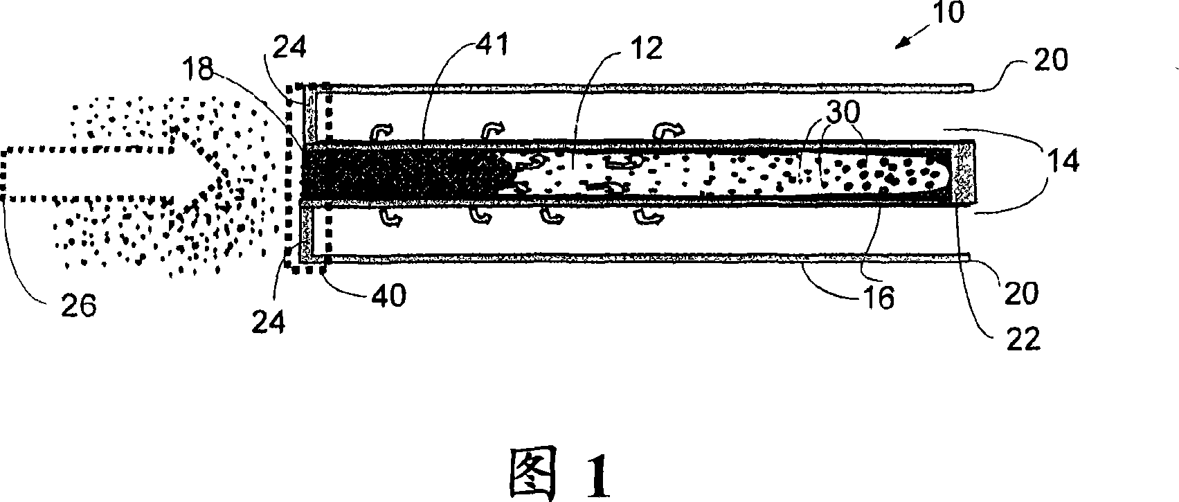
[0018] Referring now to FIG. 1 , a cross-sectional view of a portion 10 of a particulate filter (PF) is shown. The PF includes a plu...
PUM
 Abstract
Description
Claims
Application Information
 - R&D Engineer
- R&D Manager
- IP Professional
- Industry Leading Data Capabilities
- Powerful AI technology
- Patent DNA Extraction
Browse by: Latest US Patents, China's latest patents, Technical Efficacy Thesaurus, Application Domain, Technology Topic, Popular Technical Reports.
© 2024 PatSnap. All rights reserved.Legal|Privacy policy|Modern Slavery Act Transparency Statement|Sitemap|About US| Contact US: help@patsnap.com