Substrate processing apparatus
A substrate processing apparatus, a technology for substrates, applied in the directions of originals for optomechanical processing, transportation and packaging, cleaning methods and utensils, etc.
- Summary
- Abstract
- Description
- Claims
- Application Information
AI Technical Summary
Problems solved by technology
Method used
Image
Examples
no. 1 approach
[0073] Next, a substrate processing apparatus according to a first embodiment will be described with reference to the drawings.
[0074] (1-1) Structure of substrate processing apparatus
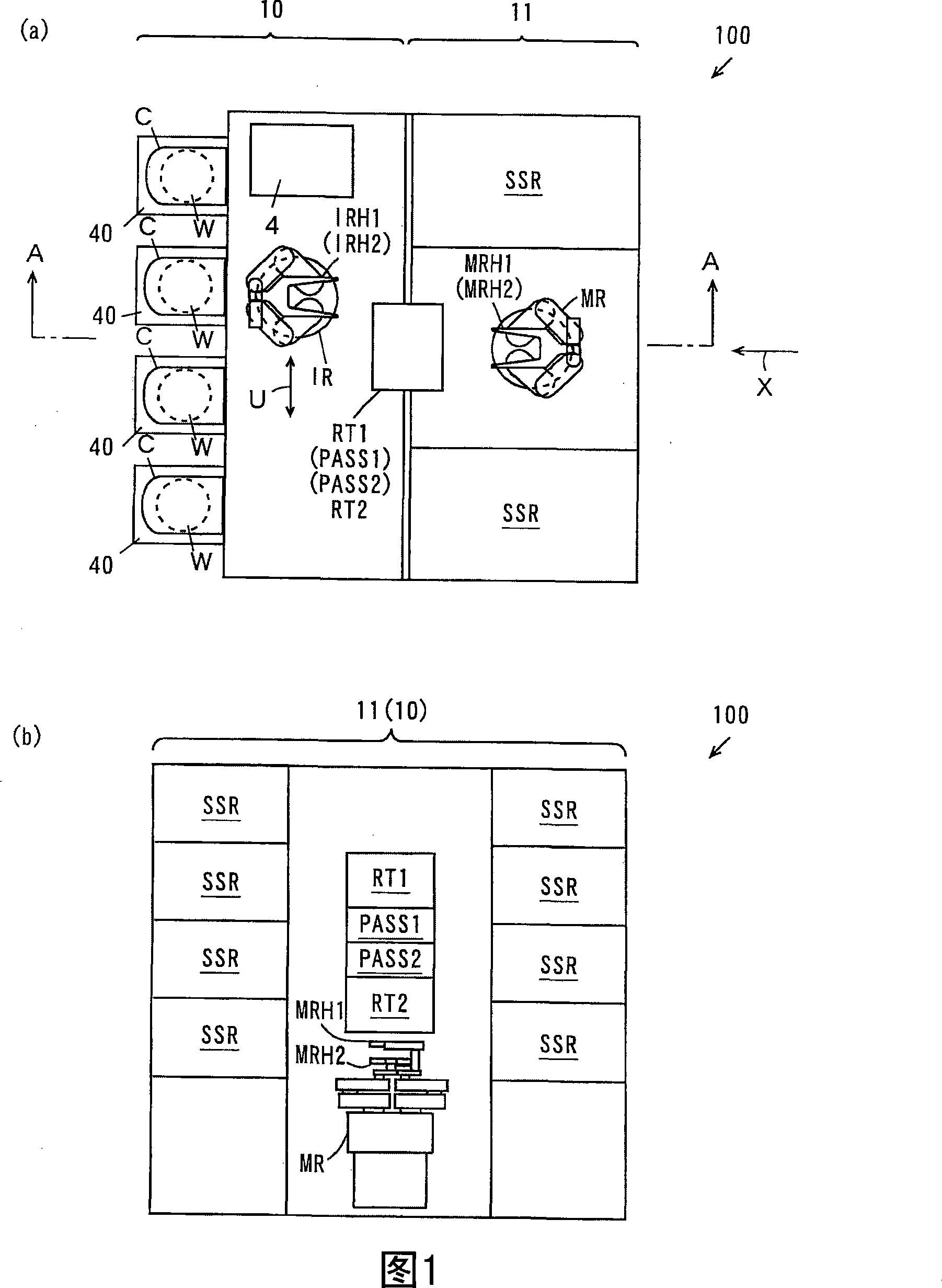
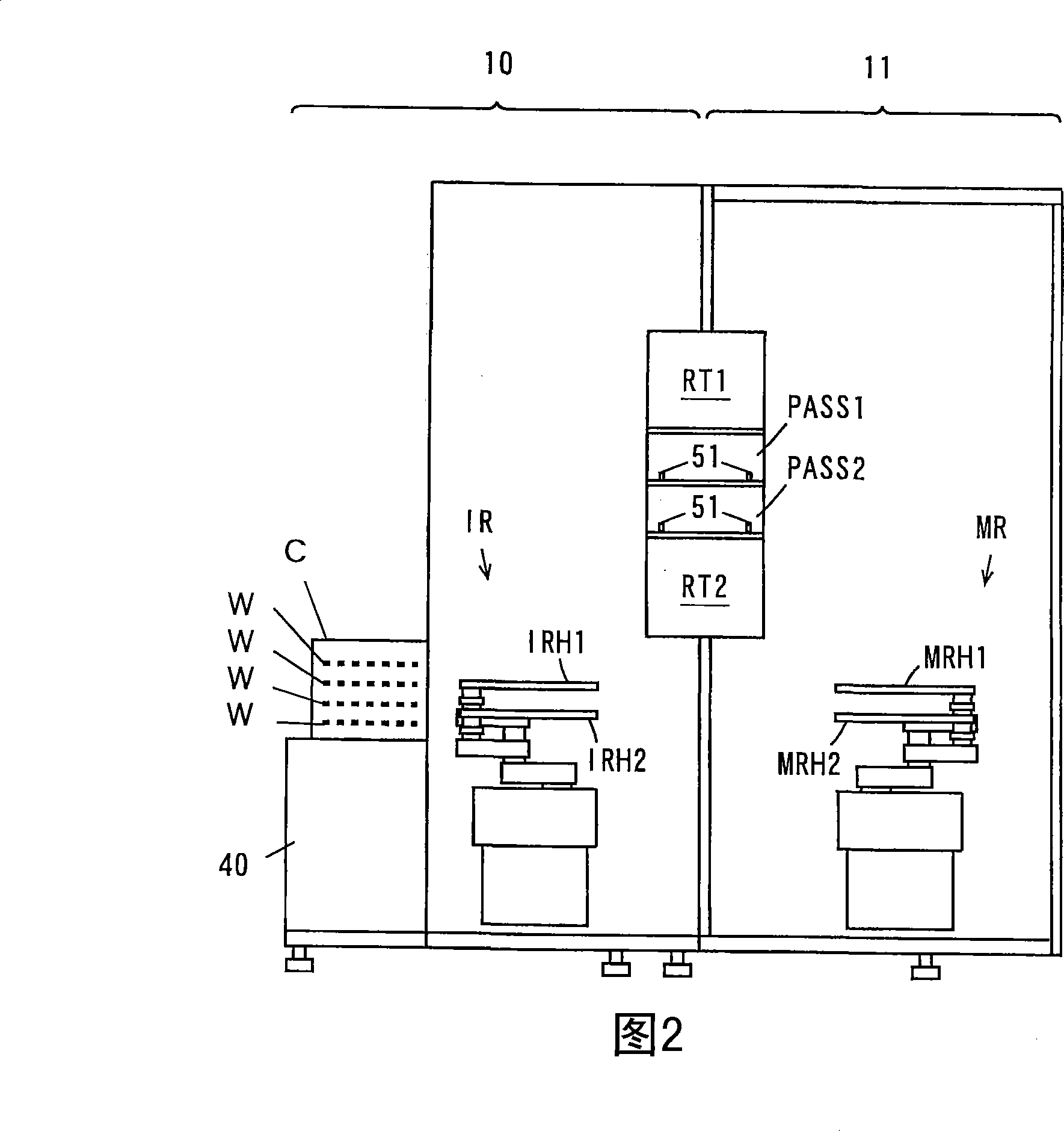
[0075] 1( a ) is a plan view showing a substrate processing apparatus according to the first embodiment, and FIG. 1( b ) is a schematic side view of the substrate processing apparatus shown in FIG. 1( a ) viewed from the direction of arrow X. In addition, FIG. 2 is a schematic diagram showing a cross section along line A-A of FIG. 1( a ).
[0076] As shown in FIG. 1( a ), the substrate processing apparatus 100 has an indexer area 10 and a processing area 11 . The indexer area 10 and the processing area 11 are arranged side by side with each other.
[0077] A plurality of carrier loading tables 40 , an indexer robot IR, and a control unit 4 are provided in the indexer block 10 . A carrier C for accommodating a plurality of substrates W in multiple layers is mounted on each carrier loading ...
no. 2 approach
[0158] Next, differences between the substrate processing apparatus according to the second embodiment of the present invention and the substrate processing apparatus according to the first embodiment will be described.
[0159] (2-1) Structure of substrate processing apparatus
[0160] FIG. 10( a ) is a plan view of a substrate processing apparatus according to a second embodiment of the present invention, and FIG. 10( b ) is a schematic view of a section along line B-B of FIG. 10( a ). As shown in FIG. 10( a ) and FIG. 10( b ), the substrate processing apparatus 100a according to the second embodiment includes two reversing units RT1 and RT2 and two substrate mounts PASS1 and PASS2 respectively. The reversing unit RT1 is vertically adjacent to the two substrate mounts PASS1 , and the reversing unit RT2 is vertically adjacent to the two substrate mounts PASS2 .
[0161] (2-2) Action of the main manipulator
[0162] The outline of the operation of the master robot MR in the ...
no. 3 approach
[0177] Next, differences between the substrate processing apparatus according to the third embodiment of the present invention and the substrate processing apparatus according to the first embodiment will be described. In the substrate processing apparatus of the third embodiment, the following reversing units RT1a, RT2a are provided instead of the reversing units RT1, RT2.
[0178]Fig. 13(a) is a side view of reversing units RT1a, RT2a, and Fig. 13(b) is a perspective view of reversing units RT1a, RT2a. The difference between reversing units RT1a, RT2a and reversing units RT1, RT2 will be described using FIG. 13(a) and FIG. 13(b). In addition, the reversing units RT1a, RT2a have the same configuration as each other.
[0179] As shown in Figure 13(a) and Figure 13(b), the overturning units RT1a, RT2a include a third movable plate 41a, a fourth movable plate 41b, a pair of linear guide rails 42a, 42b, and a pair of cylinders 43a, 43b To replace the fixed plate 32.
[0180] T...
PUM
 Abstract
Description
Claims
Application Information
 - R&D
- Intellectual Property
- Life Sciences
- Materials
- Tech Scout
- Unparalleled Data Quality
- Higher Quality Content
- 60% Fewer Hallucinations
Browse by: Latest US Patents, China's latest patents, Technical Efficacy Thesaurus, Application Domain, Technology Topic, Popular Technical Reports.
© 2025 PatSnap. All rights reserved.Legal|Privacy policy|Modern Slavery Act Transparency Statement|Sitemap|About US| Contact US: help@patsnap.com


