Electric rotating machine

A technology for rotating electrical machines and rotating shafts, applied in electrical components, electromechanical devices, electric components, etc., can solve problems such as false detection of rotor position, and achieve the effect of reducing magnetic field strength and interference level.

Inactive Publication Date: 2008-08-20
MITSUBISHI ELECTRIC CORP
View PDF1 Cites 11 Cited by
  • Summary
  • Abstract
  • Description
  • Claims
  • Application Information

AI Technical Summary

Problems solved by technology

[0005] In the control-device-integrated motor described in Patent Document 1, since the inverter circuit portion including the switching elements and the rotational position detector of the rotor are arranged close to each other, the disturbance caused by the above-mentioned sudden change in the magnetic field interferes with the rotational position detector. The output superimposition, resulting in the problem of false detection of the rotor position

Method used


Image

  • Electric rotating machine
  • Electric rotating machine
  • Electric rotating machine

Examples


Embodiment Construction

[0040] Embodiments of the present invention will be described below with reference to the drawings. Embodiments described below take as an example a structure of a control-device-integrated rotating electric machine in which a control device having a switching element unit for controlling current supplied to windings provided on a stator and a rotor is mounted on the rotating electric machine.

[0041] Embodiment 1

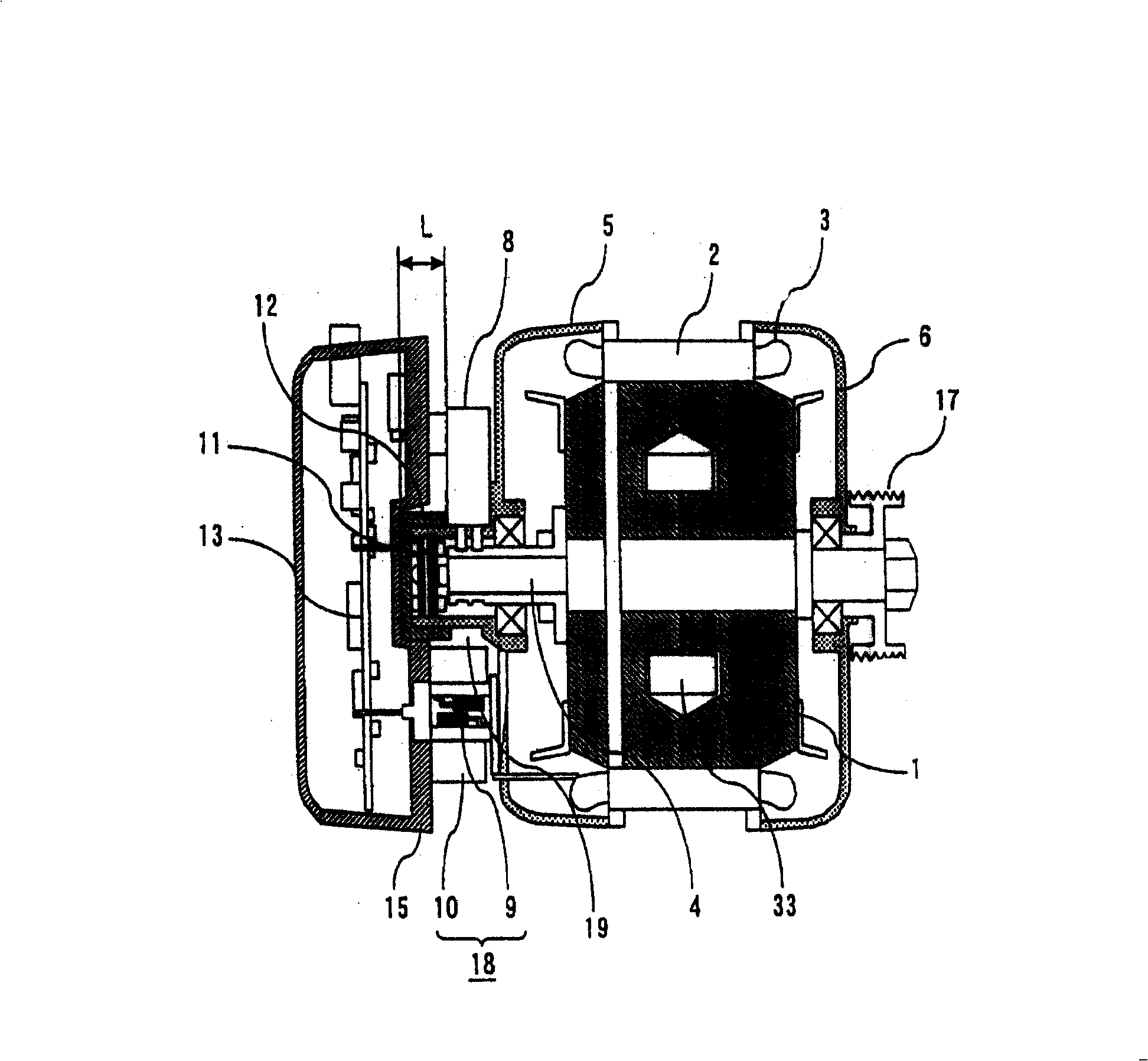
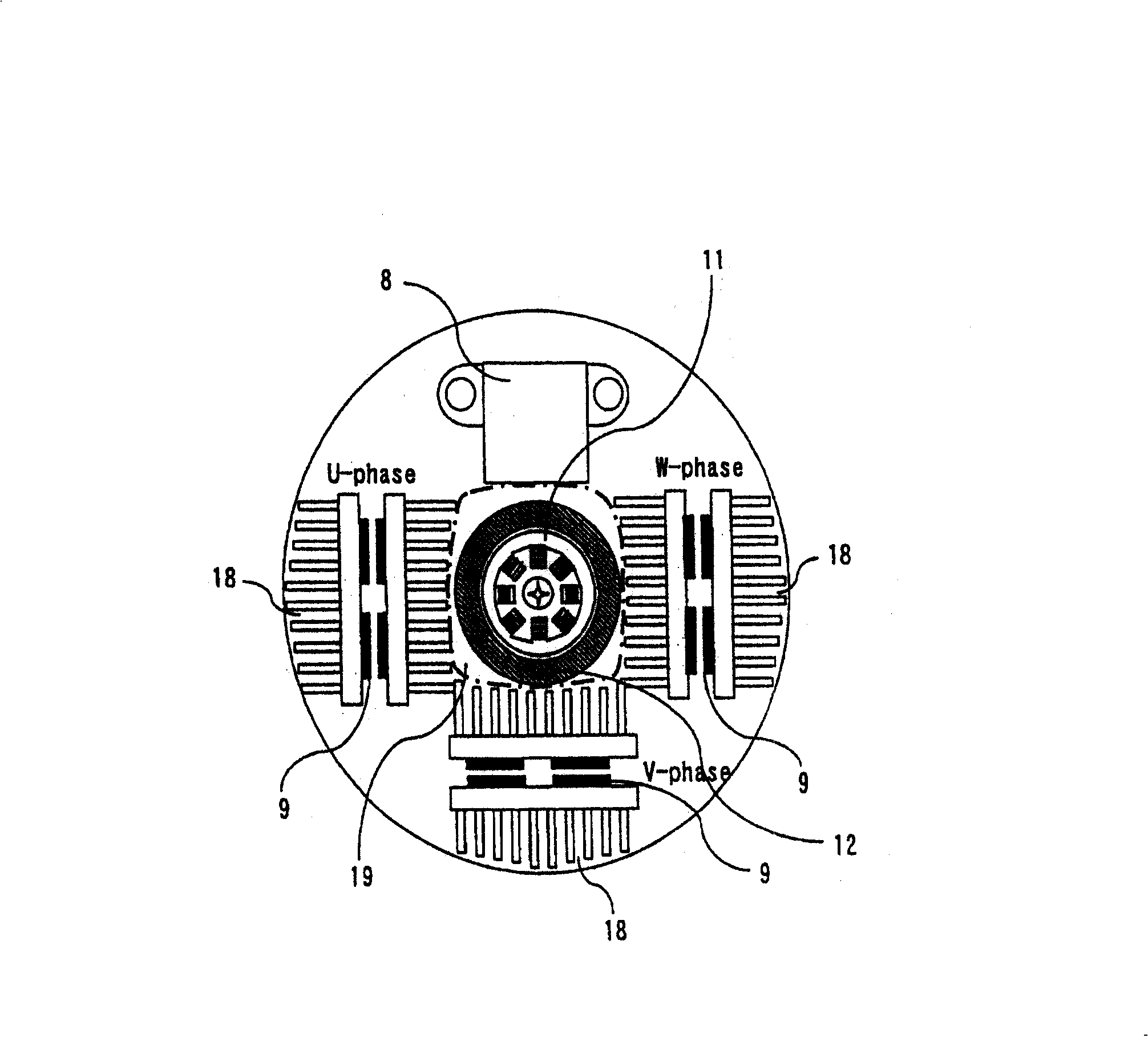
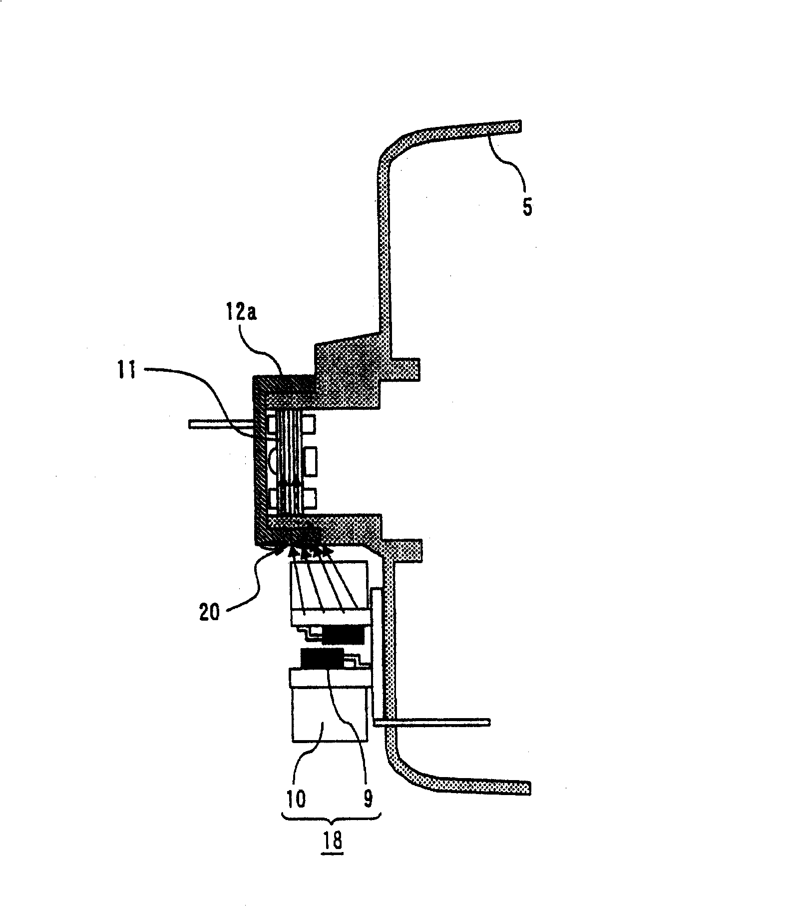
[0042] figure 1 is a schematic cross-sectional view showing Embodiment 1 of the rotating electric machine related to the present invention, figure 2 It is a side view of the periphery of the rotational position detection unit viewed from the axial direction. The rotating electrical machine in Embodiment 1 has: a stator 2 supported and fixed on end covers 5, 6; rotor 1. The stator 2 has a stator winding 3 and the rotor 1 has a rotor winding 33 . The pulley 17 is attached to the load side of the rotary shaft 4, and the pulley 17 is connected to a load not show...


PUM


Abstract

The present invention leads to that the rotating position detector is not effected by the outer magnetic field, reduces the interference included in the output of the rotating position detector and prevents the false action of the rotating position detector. The rotating electric machine comprises the following components: a stator (2); a rotor (1) which has a rotation axis (4) and rotates axially with the stator (2); end caps (5) and (6) which support and fix the stator (2) and at the same time support the rotation axis (4) to facilitate the rotation; a rotating position detecting part (11) which is arranged on the rotation axis (4) at the side opposite to the load and detects the rotating position of the rotor (1); and a power part (18) which is arranged at the external circumferential side of the rotating position detecting part (11) and is provided with a switching element (9). In the rotating electric motor the rotating position detecting part (11) is arranged with a shielding component (12) which covers the external circumference to shield the magnetic field generated by the switching element (9).

Description

technical field [0001] The present invention relates to a rotating electrical machine such as a motor, and more particularly to a small rotating electrical machine provided in a small space for use in a vehicle or the like, having a rotational position detection unit and a switching element unit for controlling current of the rotating electrical machine. Background technique [0002] For example, in the control-device-integrated motor disclosed in Patent Document 1, the control-device housing is fixed on the end cover or frame on the opposite side of the motor from the load side, and the cooling fan is installed on the sum of the rotating shaft penetrating through the control-device housing. on the end opposite the load side. An inverter circuit and a rotor position detector arranged on an inner peripheral side of the inverter circuit are installed in the controller case. [0003] [Patent Document 1] Japanese Unexamined Patent Publication No. 11-27903 (pp. 4-5, figure 2 ) ...

Claims


Application Information

Patent Timeline
Patent Type & Authority Applications(China)
IPC IPC(8): H02K11/00H02K11/02H02K29/06H02K11/01H02K11/21
Inventor 菊池正雄矶田仁志
Owner MITSUBISHI ELECTRIC CORP
Why Eureka
Try Eureka