Rotary cutting pick and method of using a cutting pick for mining

A cutting-edge technology, used in earth-moving drilling, slitting machinery, construction, etc., can solve problems such as wear and tear, and achieve the effect of reliable wear protection

Inactive Publication Date: 2008-08-20
SANDVIK INTELLECTUAL PROPERTY AB
View PDF3 Cites 12 Cited by
  • Summary
  • Abstract
  • Description
  • Claims
  • Application Information

AI Technical Summary

Problems solved by technology

[0006] The highly severe environment in which the pick operates can also cause wear on the part of the pick that comes into contact with the ground being mined

Method used


Image

  • Rotary cutting pick and method of using a cutting pick for mining

Examples


Embodiment Construction

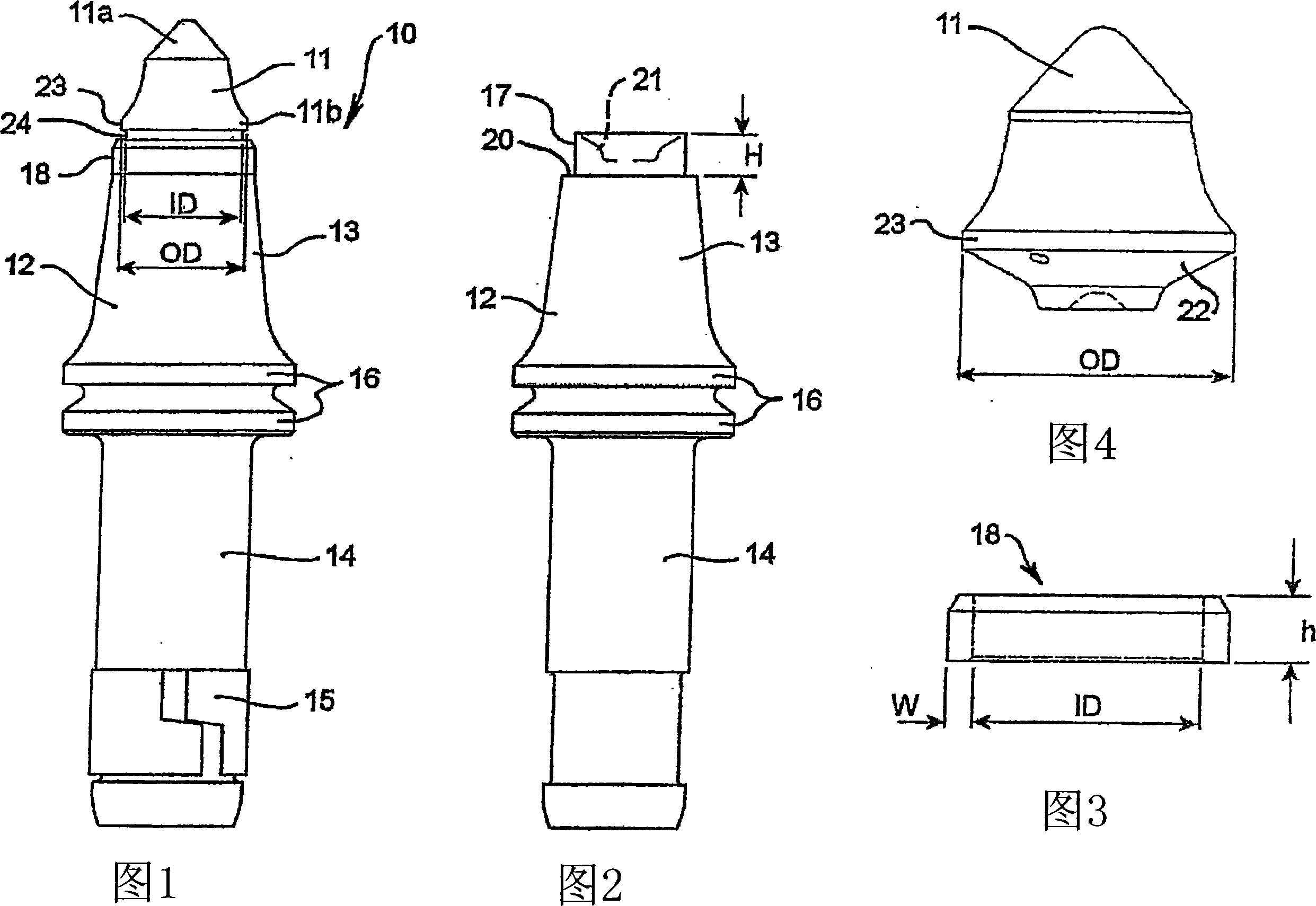
[0044] Figure 1 is a side view of a pick 10 according to the present invention. Pick 10 includes a cutting tip 11 having a leading end 11 a and a trailing end 11 b secured to an elongated shank 12 . The shank 12 includes a conical portion 13 and a cylindrical portion 14 . The cylindrical portion 14 has an attachment mechanism 15 for attaching the pick 10 to a rotating cutting drum or the like, while the pick 10 also includes a pair of flanges 16 which also facilitate mounting the pick 10 to a rotating cutting drum or the like. on the cutting barrel. The manner in which the pick 10 is mounted to the rotating cutting cartridge is not part of the invention and will be apparent to those skilled in the art.

[0045] The pick 10 also includes a cylindrical portion 17 ( FIG. 2 ) and an annular sleeve 18 extending around the cylindrical portion 17 , the sleeve 18 being located near the trailing end 11 b of the cutting tip 11 . The annular sleeve 18 is arranged to be supported on a ...


PUM


Abstract

A rotary pick (10) includes an elongated shank (12) and a cutting tip (11) mounted to one end of the shank (12). The cutting tip 11 has a front end (11a), a tail end (11b) and a mounting portion (22) for mounting to a shank (12). The tip (11) has a shape diverging outwards up to a maximum diameter portion in the direction from the leading end (11a) to the trailing end (11b). An annular sleeve (18) is attached around the shank (12) and is adjacent and in non-contacting relationship to the trailing end (11b) of the cutting tip (11). The maximum diameter (23) of the cutting tip (11) is greater than the diameter of the inner diameter of the annular sleeve (18), such that the maximum diameter portion (23) radially overlaps the sleeve (18).

Description

technical field [0001] The present invention relates to a cutting tool for mining and excavation purposes. The invention was primarily developed for the mining of coal and in use is generally used in underground coal mining. It is therefore convenient to describe the invention for this application, but it will be readily understood that the invention may also be used in any mining or excavation operation in which it can function suitably. Background technique [0002] Many different forms of equipment and machines may be used in mining and excavation operations, and generally the type of mining or excavation being conducted and the type of land being mined or excavated determines the appropriate type of equipment and machine. The present invention relates generally to underground coal mining and the safety and maintenance issues associated with the form of mining. Regarding safety issues, one of the major safety challenges in underground coal mining involves fires or explo...

Claims


Application Information

Patent Timeline
Patent Type & Authority Applications(China)
IPC IPC(8): E21C35/183E21B10/573
CPCE21C35/183E21C35/1837
Inventor 史蒂文·韦弗
Owner SANDVIK INTELLECTUAL PROPERTY AB
Why Eureka
Try Eureka