Hydraulic cylinder as well as drive unit for accelerating and braking vehicle
A driving device and hydraulic cylinder technology, applied in the field of hydraulic cylinders, can solve problems such as easy operation errors, inconvenient operation, failure to play a role, etc., and achieve the effect of convenient use and good work
- Summary
- Abstract
- Description
- Claims
- Application Information
AI Technical Summary
Problems solved by technology
Method used
Image

Examples
Embodiment Construction
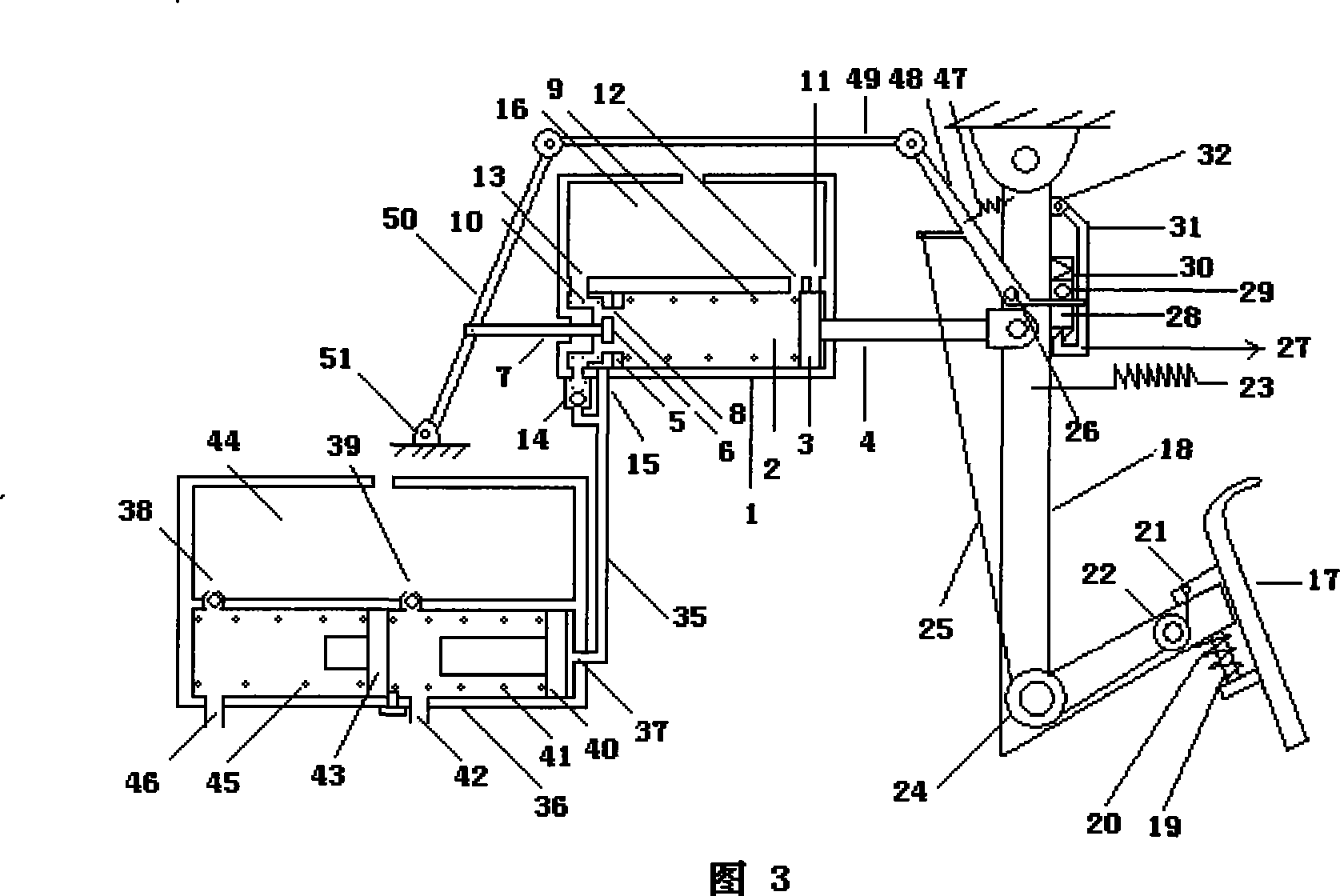
[0013] Below in conjunction with accompanying drawing, hydraulic cylinder of the present invention and automobile acceleration and brake driving device are described in detail:
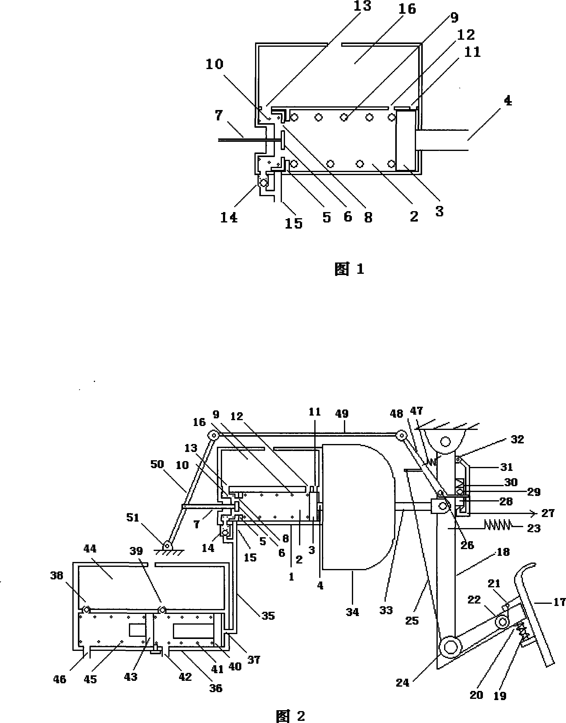
[0014] In Fig. 1, the hydraulic cylinder consists of oil cylinder 2, piston 3, push rod 4, spring seat 5, spool valve 6, spool valve rod 7, spool valve hole 8, spring 9, spring 10, oil return hole 11, oil supply hole 12 , Oil hole 13, valve 14, oil outlet hole 15, oil storage tank 16 and form.
[0015] When the hydraulic cylinder is not working, the piston 3 on the right side of the oil cylinder 2 is located between the oil return hole 11 and the oil supply hole 12, the slide valve 6 on the left side of the oil cylinder 2 is located between the spring seat 5 and the oil hole 13 at the top, and the spring seat 5 at the bottom. and valve 14. Spool valve rod 7 passes through the end center position of oil cylinder 2. At this time, the oil outlet hole 15 is closed, and the oil cylinder 2 and the oil sto...
PUM
 Abstract
Description
Claims
Application Information
 - R&D
- Intellectual Property
- Life Sciences
- Materials
- Tech Scout
- Unparalleled Data Quality
- Higher Quality Content
- 60% Fewer Hallucinations
Browse by: Latest US Patents, China's latest patents, Technical Efficacy Thesaurus, Application Domain, Technology Topic, Popular Technical Reports.
© 2025 PatSnap. All rights reserved.Legal|Privacy policy|Modern Slavery Act Transparency Statement|Sitemap|About US| Contact US: help@patsnap.com