Energy feeding type electrical energy mass perturbance generating device

A power quality disturbance generation device technology, applied in the direction of measuring devices, measuring electrical variables, output power conversion devices, etc., can solve the problems of high cost, long test cycle, and difficulty in unifying test environment standards, so as to save electric energy and reduce required effect

Inactive Publication Date: 2008-08-27
SOUTHEAST UNIV
0 Cites 28 Cited by

AI-Extracted Technical Summary

Problems solved by technology

Therefore, the test cycle is long, the cost is high, a...

Abstract

The present invention discloses an energy-feedback type power quality disturbance generating device, which relates to a power quality disturbance generating device. The device comprises a harmonic source (1), a feedback link (2), a middle direct current capacitor (3), a control terminal (4), a first LCL filtering link (5), and a second LCL filtering link (6). The control terminal (4) adopts a DSP controller to realize that a control signal which is generated according to the setting of a user controls the harmonic source to partially generate current disturbance. The harmonic source and the feedback link are cascaded via the middle direct current capacitor to form an AC-DC-AC topological structure so as to realize power feedback. The alternating current side of the harmonic source is connected with a power network via the first LCL filtering link. The alternating current side of the feedback link is connected with the power network via the second LCL filtering link. The device is capable of simulating harmonic current, active current, inductance reactive current or capacitive reactive current of a plurality of combination frequencies, and the device is capable of simulating various working conditions of a plurality of nonlinear loads such as electric arc furnaces, medium frequency furnaces, welding machines and frequency converters, etc.

Application Domain

Technology Topic

Image

  • Energy feeding type electrical energy mass perturbance generating device
  • Energy feeding type electrical energy mass perturbance generating device
  • Energy feeding type electrical energy mass perturbance generating device

Examples

  • Experimental program(1)

Example Embodiment

[0018] The accompanying drawings are embodiments of the present invention. The content of the present invention will be further described below in conjunction with the accompanying drawings:
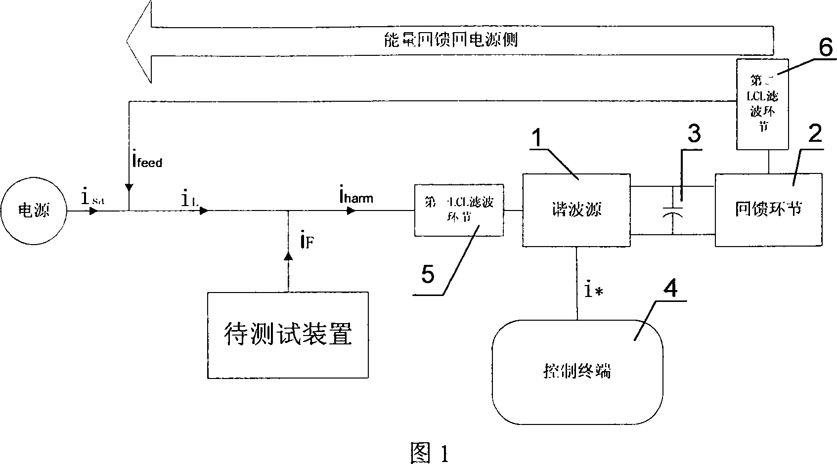
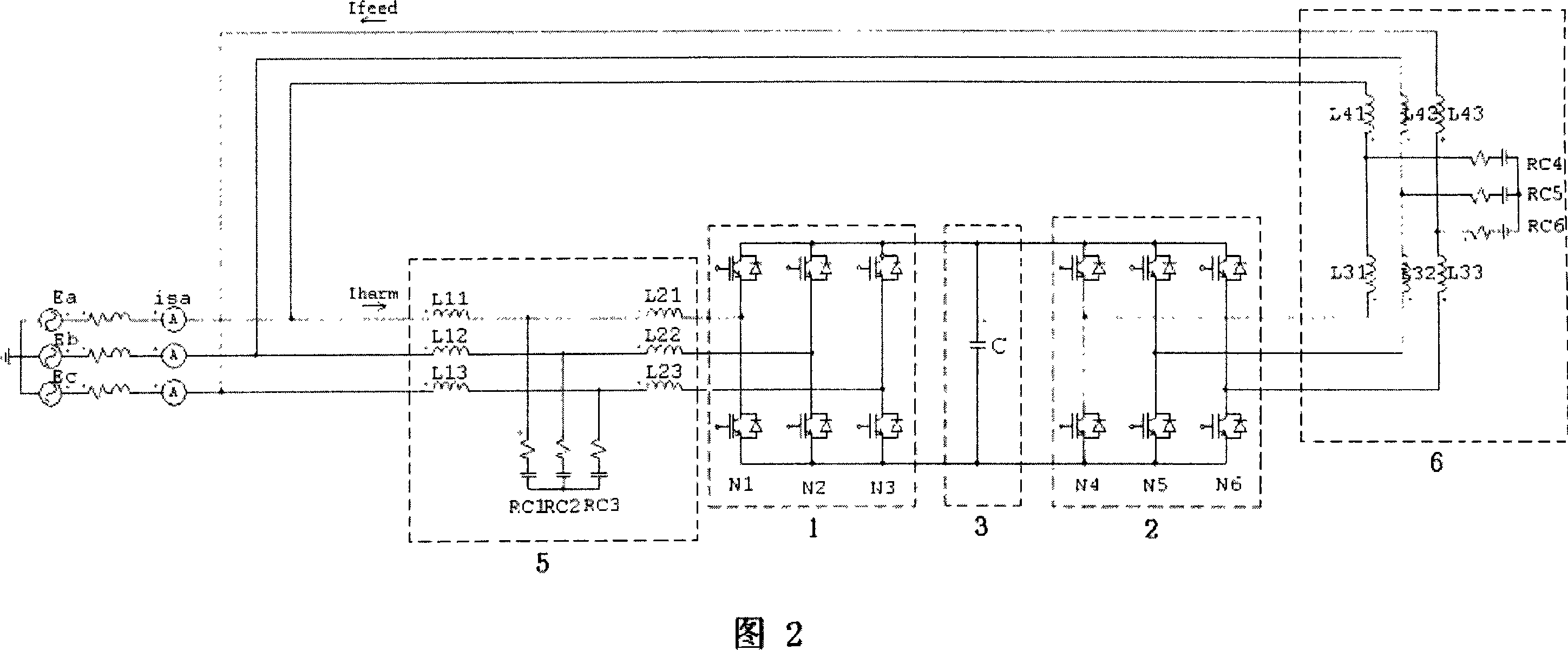
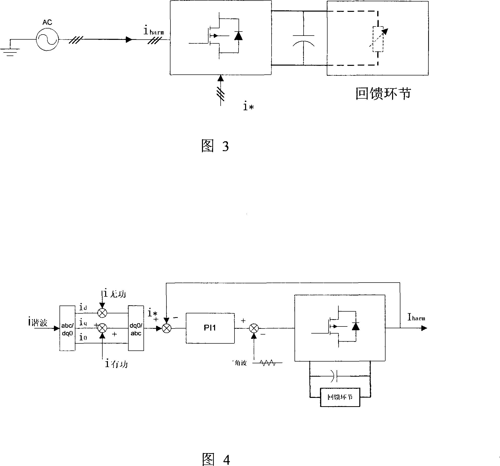
[0019] The device includes a harmonic source 1, a feedback link 2, an intermediate DC capacitor 3, a control terminal 4, a first LCL filter link 5, and a second LCL filter link 6. The control terminal 4 is implemented by a DSP controller, which is based on user settings. A control signal is always generated to control the harmonic source part to generate current disturbances; the harmonic source 1 and the feedback link 2 are cascaded through a 3-phase intermediate DC capacitor to form an AC-DC-AC topology to realize energy feedback; harmonic source 1 AC The AC side of the feedback link 2 is connected to the power grid through the first LCL filtering link 5, and the AC side of the feedback link 2 is connected to the power grid through the second LCL filtering link 6.
[0020] 1. Harmonic source
[0021] As shown in Figure 3, the harmonic source can be regarded as the nonlinear load of the power supply. It includes a first bridge arm N1, a second bridge arm N2, and a third bridge arm N3 to form a three-phase bridge PWM converter structure. The DC side of the harmonic source 1 is connected to the intermediate DC capacitor 3, and the AC side is connected to the first One end of the LCL filter link 5 is connected. The first LCL filter link 5 consists of a first inductor L11, a second inductor L12, a third inductor L13, a fourth inductor L21, a fifth inductor L22, a sixth inductor L23, and a A resistor-capacitor RC1, a second resistor-capacitor RC2 and a third resistor-capacitor RC3 form three single-phase T-type filters; among them, the midpoint of the first bridge arm N1 is connected to the fourth inductor L21, and the center of the second bridge arm N2 The point is connected to the fifth inductor L22, and the midpoint of the third bridge arm N3 is connected to the sixth inductor L23.
[0022] According to the setting of the control terminal, it will absorb current from the power grid, generate specified active and reactive power and harmonic currents, and simulate actual nonlinear loads. In this case, it itself exhibits the characteristics of a non-linear load. For the harmonic source, the feedback link is a resistive load on the DC side, and the harmonic source absorbs the power of the power source to maintain the stability of the DC side capacitor voltage.
[0023] The setting of harmonic, active and reactive current is all done by the control terminal. The harmonic current command signal is superimposed after each harmonic current is generated by the control terminal as the setting of the harmonic current. For active and reactive current, the phase angle needs to be calculated for direct setting, and the command current signal generated by the control terminal is too much to calculate, so it is not directly given. Harmonic, active and reactive current setting methods are shown in Figure 4.
[0024] The active and reactive current adopts the active and reactive current setting method based on dq0 transformation. The principle is as follows:
[0025] Suppose the infinite power grid is a symmetrical three-phase voltage without distortion, which is:
[0026] E abc = U m sin ( ωt ) sin ( ωt - 2 π 3 ) sin ( ωt + 2 π 3 )
[0027] Then the active current is:
[0028] i pabc = I pm sin ( ωt ) sin ( ωt - 2 π 3 ) sin ( ωt + 2 π 3 )
[0029] After dq0 transformation is:
[0030] i pdq 0 = Pi pabc = PI pm sin ( ωt ) sin ( ωt - 2 π 3 ) sin ( ωt + 2 π 3 ) = I pm 0 - 1 0
[0031] The reactive current is:
[0032] i qabc = I qm sin ( ωt ± π 2 ) sin ( ωt ± π 2 - 2 π 3 ) sin ( ωt ± π 2 + 2 π 3 )
[0033] After dq0 transformation is:
[0034] i qdq 0 = Pi qabc = PI qm sin ( ωt ± π 2 ) sin ( ωt ± π 2 - 2 π 3 ) sin ( ωt ± π 2 + 2 π 3 ) = I qm ± 1 0 0
[0035] Therefore, after the active current is transformed, only i q The reactive current is only related to i d Related, and both are DC components, i q And i d The magnitude is equal to the amplitude of active and reactive current respectively.
[0036] The PWM control method of the harmonic source adopts the triangular wave comparison method. The control terminal generates the command signal according to the setting, takes the actual current waveform as the feedback signal, and subtracts the feedback signal from the command signal and performs proportional integration to obtain the control current of the main circuit. The control current is used as the control signal of the main circuit switching device after PWM conversion. The control method is shown in Figure 4.
[0037] 2. Feedback link
[0038] The schematic diagram of the feedback link is shown in Figure 5. The feedback link 2 includes the fourth bridge arm N4, the fifth bridge arm N5, and the sixth bridge arm N6, which form a three-phase bridge PWM converter structure. The intermediate DC capacitor 3 is connected, and the AC side is connected to one end of the second LCL filter link 6. The second LCL filter link 6 is composed of a seventh inductor L31, an eighth inductor L32, a ninth inductor L33, and a tenth inductor L41. , The eleventh inductor L42, the twelfth inductor L43, the fourth resistor-capacitor RC4, the fifth resistor-capacitor RC5, and the sixth resistor-capacitor RC6 form three single-phase T-type filters; among them, the midpoint of the fourth bridge arm N4 It is connected to the seventh inductor L31, the midpoint of the fifth bridge arm N5 is connected to the eighth inductor L32, and the midpoint of the sixth bridge arm N6 is connected to the ninth inductor L33.
[0039]The capacitance of the main circuit and the capacitance in the harmonic source are the same capacitance. For the power supply, the harmonic source is a non-linear load. For the feedback link, since the capacitor is shared and the DC side capacitor voltage is almost constant, the harmonic source is equivalent to the feedback part of the DC power supply on the DC side. The feedback link will invert the DC and feedback Back to the grid to realize energy feedback.
[0040] The stability of the capacitor voltage is the key to the stability of the entire system. According to the simulation results, the stability of the capacitor voltage should be controlled by the feedback part. According to the theory of instantaneous reactive power (also known as pq theory), for a PWM inverter, instantaneous reactive power does not cause energy exchange between the AC side and the DC side. The sum of the instantaneous active power of each phase circuit is equal to the instantaneous active power p of the three-phase circuit. That is to say, for a PWM inverter, if the loss of each part is not considered, the instantaneous active power of the AC side will be all transferred to the DC side, that is, the energy exchange between the AC side and the DC side depends on the instantaneous active power, and Reactive power is irrelevant.
[0041] Therefore, to control the stability of the capacitor voltage, it is only necessary to control the active power (that is, the active current), and the active current is only related to i q related. The proportional integral controller PI3 subtracts the DC side capacitor voltage from the reference voltage and performs proportional integration to obtain the current Δi required to maintain the capacitor voltage stability q (Figure 6).
[0042] The PWM control method of the feedback link is the same as that of the harmonic source part, and the triangular wave comparison method is still used. The command signal is determined by the load current i l It is superimposed with the active current that keeps the capacitor voltage stable, as shown in Figure 6. The actual feedback current waveform is used as the feedback signal, and the command signal is subtracted from the feedback signal and then proportionally integrated to obtain the control current of the main circuit. After PWM conversion, the control current is used as the control signal of the main circuit switching device.

PUM

no PUM

Description & Claims & Application Information

We can also present the details of the Description, Claims and Application information to help users get a comprehensive understanding of the technical details of the patent, such as background art, summary of invention, brief description of drawings, description of embodiments, and other original content. On the other hand, users can also determine the specific scope of protection of the technology through the list of claims; as well as understand the changes in the life cycle of the technology with the presentation of the patent timeline. Login to view more.

Similar technology patents

Classification and recommendation of technical efficacy words

  • Lower requirement
  • Save electricity

LTE channel measurement and feedback method

InactiveCN102546113ALower requirementReduce computational workloadError preventionTransmission path multiple useSignal-to-noise ratio (imaging)Transmission point
Owner:沈阳市联盛科技有限公司

Crude oil pulsing electrical desalting technique

InactiveCN101037612ASave electricityDewatering/demulsification with electric/magnetic meansWater contentPulse frequency
Owner:CHINA PETROLEUM & CHEM CORP
Why Eureka
Try Eureka