Supercharge Your Innovation With Domain-Expert AI Agents!

Annular satellite navigation aerial and manufacturing method thereof

A satellite navigation antenna and ring technology, applied in the field of satellite navigation antennas, can solve the problems that it is difficult to meet the requirements of satellite navigation receivers, low elevation gain, flat panel antenna impedance bandwidth and narrow circular polarization bandwidth, so as to avoid feeding network, The effect of high gain and high industrial application value

Inactive Publication Date: 2012-05-30
BEIHANG UNIV
View PDF0 Cites 0 Cited by
  • Summary
  • Abstract
  • Description
  • Claims
  • Application Information

AI Technical Summary

Problems solved by technology

However, with the conventional design method, the impedance bandwidth and circular polarization bandwidth of the panel antenna are narrow, and the low elevation gain is difficult to meet the requirements of the satellite navigation receiver

Method used


Image

  • Annular satellite navigation aerial and manufacturing method thereof
  • Annular satellite navigation aerial and manufacturing method thereof
  • Annular satellite navigation aerial and manufacturing method thereof

Examples


Embodiment Construction

[0028] The present invention will be described in detail below in conjunction with the accompanying drawings and specific embodiments.

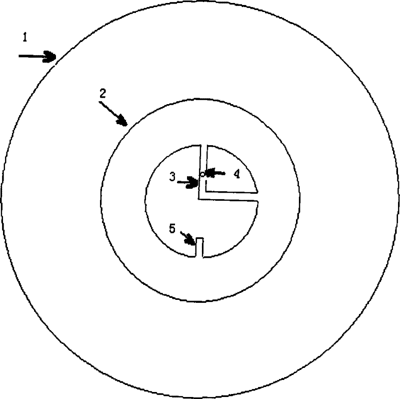
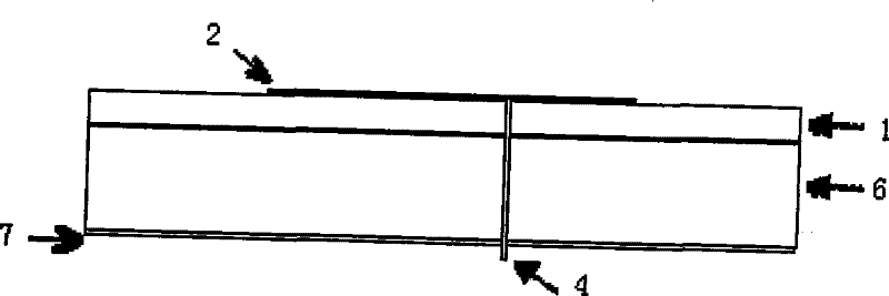
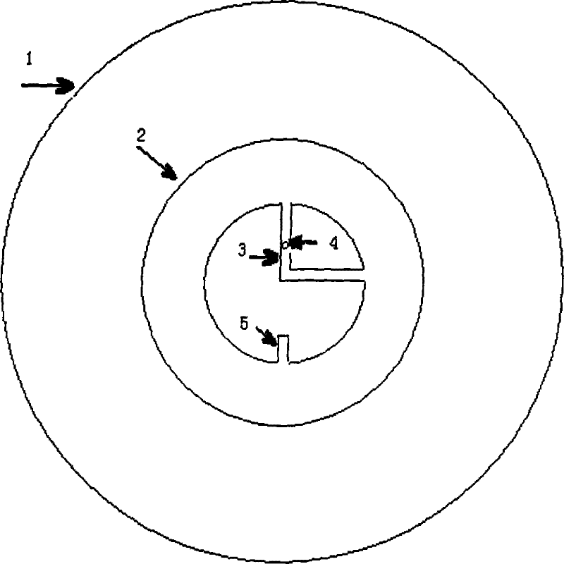
[0029] Such as figure 1 and figure 2 As shown, the structure of the present invention includes: a microwave substrate 1, an annular patch antenna 2, two feeding branches 3, a feeding probe 4, a disturbing branch 5, a foam support substrate 6, a metal grounding plate 7, and an annular patch The chip antenna 2 is located on the upper surface of the microwave substrate 1, and the foam support substrate 6 is located below the circular microwave substrate 1 to support the microwave substrate 1; the metal ground plate 7 is located below the foam support substrate 6, and each feeding branch 3 One end is connected to the inner edge of the loop patch antenna 2, and the other end is interconnected, and the two branches are designed vertically; a disturbance branch 5 is designed on the opposite side of a feeding branch 3, one end is open, and the othe...


PUM


Abstract

The invention provides an annular satellite navigation antenna which includes: a microwave substrate, a foam support substrate, a metal ground plate, an annular patch antenna, two feeding branches, a disturbance branch, a feeding probe; the annular patch antenna is located on upper surface of the microwave substrate, the foam support substrate is located on down part of the microwave substrate; the metal ground plate is located on down part of the foam support substrate, one end of each feeding branch connects with the annular patch antenna inside edge, another end connects each other, two feeding branches are mutually perpendicular; the disturbance branch is designed on opposite side to one feeding branch, one end opens circuit, and another end connects with the annular patch annular inside edge; the feeding probe connects with the feeding branch through the metal ground plate, the foam supporting substrate and the microwave substrate, and feeds to the annular patch antenna; then, the antenna is manufactured by using photoengraving or lithography corrosion; the antenna has higher low elevation gain, more wide bandwidth, simple structure, and is easy to process, especially is convenient as antenna array unit.

Description

technical field [0001] The invention relates to a satellite navigation antenna, in particular to a circular satellite navigation antenna with a simple structure and easy to form an array and a preparation method thereof. Background technique [0002] With the vigorous development of satellite navigation and positioning technology, countries have developed their own global satellite navigation systems. The stability and reliability of the system put forward higher requirements. Therefore, it has become a technical hotspot to design an antenna system that can receive multiple satellite navigation signals at the same time and provide continuous and stable satellite navigation signals. [0003] A satellite navigation terminal is at least composed of a receiver and an antenna. The main function of the antenna is to receive navigation signals, so the design of the antenna is particularly important for the quality of the navigation system. Today's antenna design must not only meet...

Claims


Application Information

Patent Timeline
Patent Type & Authority Patents(China)
IPC IPC(8): H01Q1/38H01Q7/00H01Q1/22H05K3/06
Inventor 吕善伟张英锋张岩
Owner BEIHANG UNIV
Features
  • R&D
  • Intellectual Property
  • Life Sciences
  • Materials
  • Tech Scout
  • Unparalleled Data Quality
  • Higher Quality Content
  • 60% Fewer Hallucinations
Learn More