Blade device for working machine and working machine mounted with the same
A technology for construction machinery and shovel blades, which is applied in the field of shovel blades and can solve the problems such as the sliding of the connecting front part of the central front part to the outer side, the sliding of the front part of the end part, and the reduction of excavation efficiency.
Inactive Publication Date: 2008-09-03
KOMATSU LTD
View PDF2 Cites 5 Cited by
- Summary
- Abstract
- Description
- Claims
- Application Information
AI Technical Summary
Problems solved by technology
Therefore, this composition will greatly reduce the mining efficiency
In addition, depending on the design of the central front, connecting front and end fronts, there is a low probability of having a blade that digs less efficiently than a prior art semi-U-shaped blade of the same blade capacity
In addition, especially in the case of rotating and pressing down when moving soil, the soil carried on the blade will slide from the central front to the outer connecting front in a very short period of time during the rotating travel, and will fall from the front of the end. The phenomenon of slipping everything in an instant
Method used
View moreImage
Smart ImageViewing Examples
Examples
Embodiment 2
[0228] Next, a blade (blade for construction machinery) 50 equipped with a fence (baffle member) 70 according to another embodiment of the present invention will be described with reference to FIGS. 27 to 33 .
[0229] In addition, as for the direction of "front and rear" used in the following description, the forward direction of the bulldozer is defined as "front", and the backward direction is defined as "rear".
Login to View More PUM
 Abstract
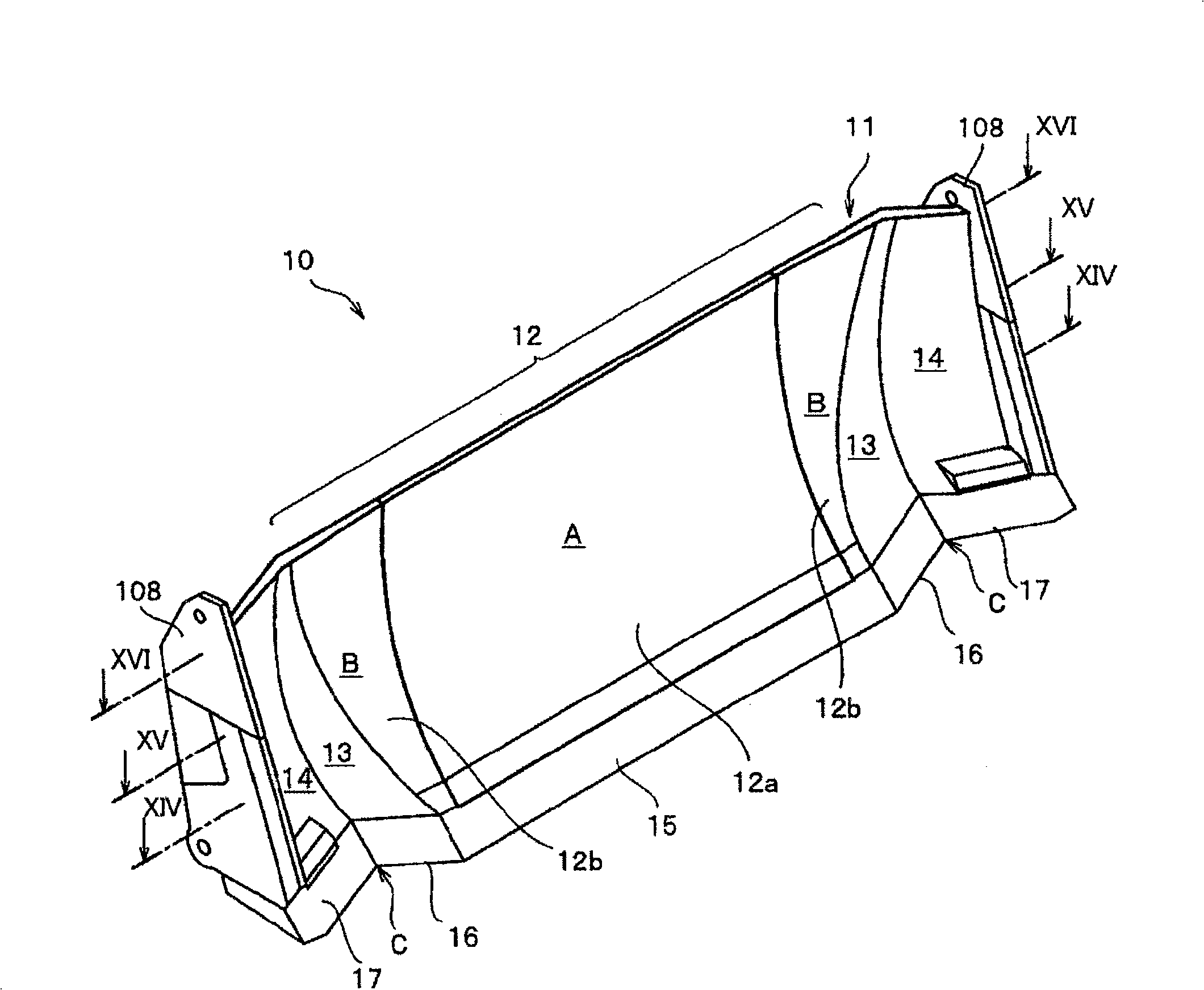
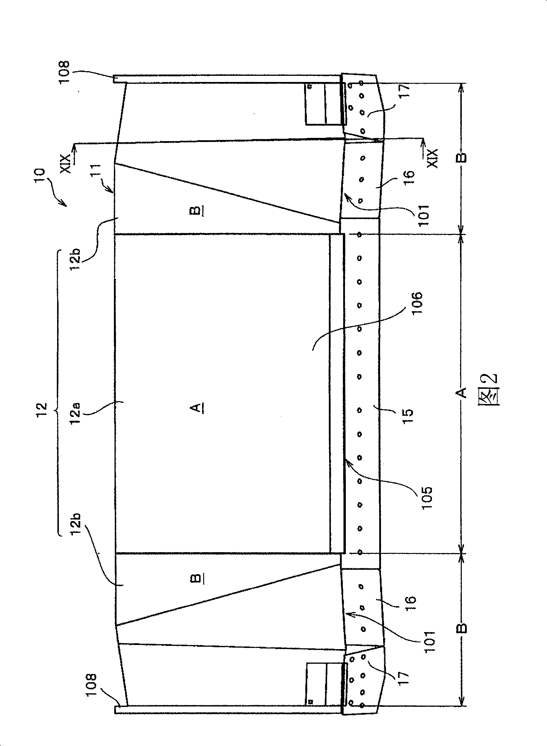
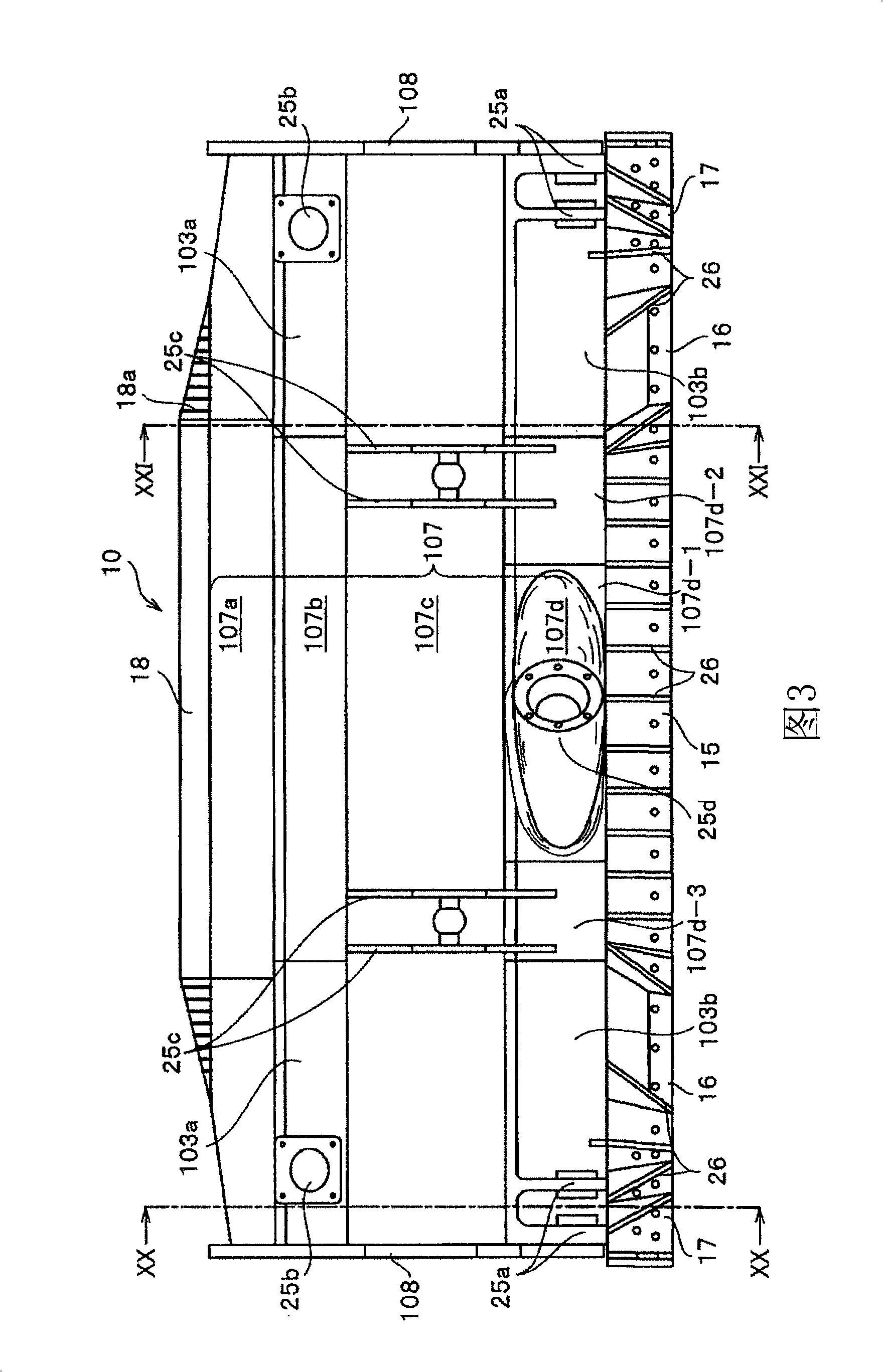
The present invention provides a blade deice for a working machine, having an overall blade width of W, and having a center front-face section (12) that has at its lower end a rectilinear first cutting blade (15) with a predetermined blade width (W1), connection front-face sections (13) each having a second cutting edge (16) that extends rearward continuous from the first cutting blade (15) and bent at a predetermined angle d relative to the first edge (15), and end front-face sections (14) each having a third cutting edge (17) that extends continuous from the second cutting blade (16) and is bent at an angle theta relative to a line extended from the first cutting blade (15). When each cutting blade (15-17) extends in a tangential direction from the lower end of each front-face sections (12-14), a blade edge angle a of each cutting blade (15-17) is in a cutting position in a rage of 40 DEG - 55 DEG , and the height, in a side view, from the edge of the first cutting blade (15) to the upper end of the blade is H, the blade device satisfies the following expression: R2 = (0.7 to 1.0) H ...(1).
Description
technical field [0001] The present invention relates to a shovel loaded on various engineering vehicles such as bulldozers or wheeled bulldozers, and in particular to an engineering machinery shovel suitable for excavation, soil transportation, leveling, etc., with good operating efficiency, improved fuel efficiency and economy Knife device and engineering machinery with the device. Background technique [0002] Various construction vehicles such as bulldozers and wheeled bulldozers are often used at various work sites such as construction and civil engineering. This engineering vehicle is loaded with engineering attachments, ie blades. The blade is widely used in bulldozing operations such as excavation, soil transportation, soil filling, soil compaction, and leveling. [0003] In this kind of engineering vehicle, in order to maximize its operating efficiency, the key is to meet the following conditions: that is, to increase the amount of soil transported in each cycle (s...
Claims
Login to View More Application Information
Patent Timeline
 IPC IPC(8): E02F3/815
Inventor 松本典久和田达夫
Owner KOMATSU LTD
Features
- R&D
- Intellectual Property
- Life Sciences
- Materials
- Tech Scout
- Unparalleled Data Quality
- Higher Quality Content
- 60% Fewer Hallucinations
Learn More Browse by: Latest US Patents, China's latest patents, Technical Efficacy Thesaurus, Application Domain, Technology Topic, Popular Technical Reports.
© 2025 PatSnap. All rights reserved.Legal|Privacy policy|Modern Slavery Act Transparency Statement|Sitemap|About US| Contact US: help@patsnap.com


