Liquid self-absorbing air purifier

An air purifier and self-priming technology, applied in chemical instruments and methods, using liquid separators, dispersing particle separation, etc., can solve the problems of small contact area of ​​leaves, limited water adhering to the surface, weak purification effect, etc. The effect of good gas passage, long contact time and high purification efficiency

Inactive Publication Date: 2008-09-10
姜大坚
View PDF0 Cites 0 Cited by
  • Summary
  • Abstract
  • Description
  • Claims
  • Application Information

AI Technical Summary

Benefits of technology

This technology allows for efficient separation of liquids from gases by creating very small areas on its surfaces that allow them to flow through easily with minimal resistance or pressure loss during use compared to traditional methods like membranes.

Problems solved by technology

This technical problem addressed by this patented technology relates to improving domestic air cleanliness with low noise equipment such as an oven ventilator (OV). However, current methods have limitations due to their costly design and lack of effective treatments at smaller sources like restaurants' waste gases.

Method used


Image

  • Liquid self-absorbing air purifier

Examples


Embodiment Construction

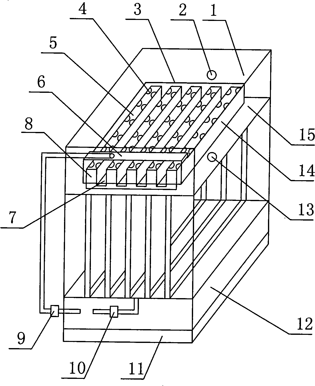
[0022] The present invention will be further described below in conjunction with accompanying drawing.

[0023] refer to figure 1 , the present embodiment includes a box body 1 provided with a liquid overflow port 2, the lower part of the box body 1 is provided with a main liquid tank 15 along the horizontal direction of the box wall, and the main liquid tank 15 is surrounded by four liquid separation tanks 7. Groove 15 is communicated with liquid separation tank 7, and liquid separation tank 7 walls are provided with deflector frame 8, and deflector frame 8 is provided with deflector 5, between deflector frame 8 inner wall and deflector 5 An upright deflector tube 4 is provided; the top of the deflector frame 8 and the deflector 5 is provided with a flat cover 3, and between the top of the flat cover 3 and the common top of the deflector frame 8 and the deflector 5 and the flat cover 3 A flat cover bracket is provided; a pressure exchange chamber 6 connected to the flat cove...


PUM

PropertyMeasurementUnit
Vertical heightaaaaaaaaaa
Widthaaaaaaaaaa
Lengthaaaaaaaaaa

Abstract

A liquid self-priming current air cleaner comprises a box body. A main flume is arranged at the lower part inside the box body along the horizontal direction, the main flume is surrounded with at least three branched flumes, the main flume is communicated with the branched flumes, a guide vane is arranged on the wall body of the branched flumes, the stream guidance frame is provided with a guide vane; a vertical guide vane is arranged between the inner wall of the guide vane and the surface of the guide vane; a slab cover is arranged at the top part of the stream guidance frame and the guide vane; a slab cover support is arranged between the common top of the stream guidance frame and the guide vane and the slab cover; a pressure switch room connected with the slab cover is arranged above the main flume, the top of the pressure switch room is higher than the top of the slab cover; a surrounding plate is arranged inside the main flume and is connected with the edges of the slab cover and the lower end of the pressure switch room; the box body is arranged on the top part of the cleaner, while a base is arranged on the lower part of the cleaner; a main liquid pump and an secondary liquid pump are also arranged on the lower part of the cleaner, one end of the main liquid pump is communicated with a circulating pool and the other end is communicated with an inlet; one end of the secondary liquid pump is communicated with the circulating pool and the other end is communicated with the pressure switch room. The invention is characterized by less energy consumption and high purification efficiency.

Description


Claims


Application Information

Patent Timeline
Owner 姜大坚
Why Eureka
Try Eureka