Hydraulic support tail beam

A technology of hydraulic support and tail beam, which is applied to mine roof support, mining equipment, earthwork drilling and other directions, can solve the problems of increasing the cost per ton of coal, inappropriate light support, and large gap between the tail beam, etc., so as to reduce the cost per ton of coal, Solve the effect of difficulty in discharging waste and difficulty in rack adjustment

Inactive Publication Date: 2011-05-04
李泽宇
View PDF5 Cites 0 Cited by
  • Summary
  • Abstract
  • Description
  • Claims
  • Application Information

AI Technical Summary

Problems solved by technology

The tail beams of these brackets are relatively narrow, and the gap between the tail beams is large, and gangue and coal are easy to leak through the gap, so the roof net must be laid when the top coal is laid, so the cost per ton of coal is increased.
In addition, because the structure of these tail booms is a two-point support, and except for the straight tail boom, they are all bent upwards, so the center of gravity of the tail boom is higher than the line connecting the two support points, so it is unstable and has a block When large gangue and coal fall between the two tail beams, the tail beam will be tilted outwards, causing the tail beam to overturn, causing danger
In the fully mechanized mining support, the tail beam is called the cover beam, which is connected with the top beam as a whole. It has high strength, but is relatively heavy. Each support weighs about ten tons, which is not suitable for light supports.
There is also a support with an integral wide tail beam, which solves the problem that the narrow tail beam made of section steel must be laid when the top coal is laid. difficulty
In addition, the lower end of this tail beam is in contact with the bottom plate by a line. Although it is not easy to fall over, there are two hinge points on the tail beam that are far apart, which are respectively hinged on both sides of the entire top beam or the entire frame bracket. The contact line at the lower end of the beam and the two hinge points on the upper side are often not in the same plane, so it will be distorted and deformed when subjected to the pressure of gangue, and sometimes the top beam and tail beam will be damaged.

Method used


Image

  • Hydraulic support tail beam
  • Hydraulic support tail beam
  • Hydraulic support tail beam

Examples


Embodiment Construction

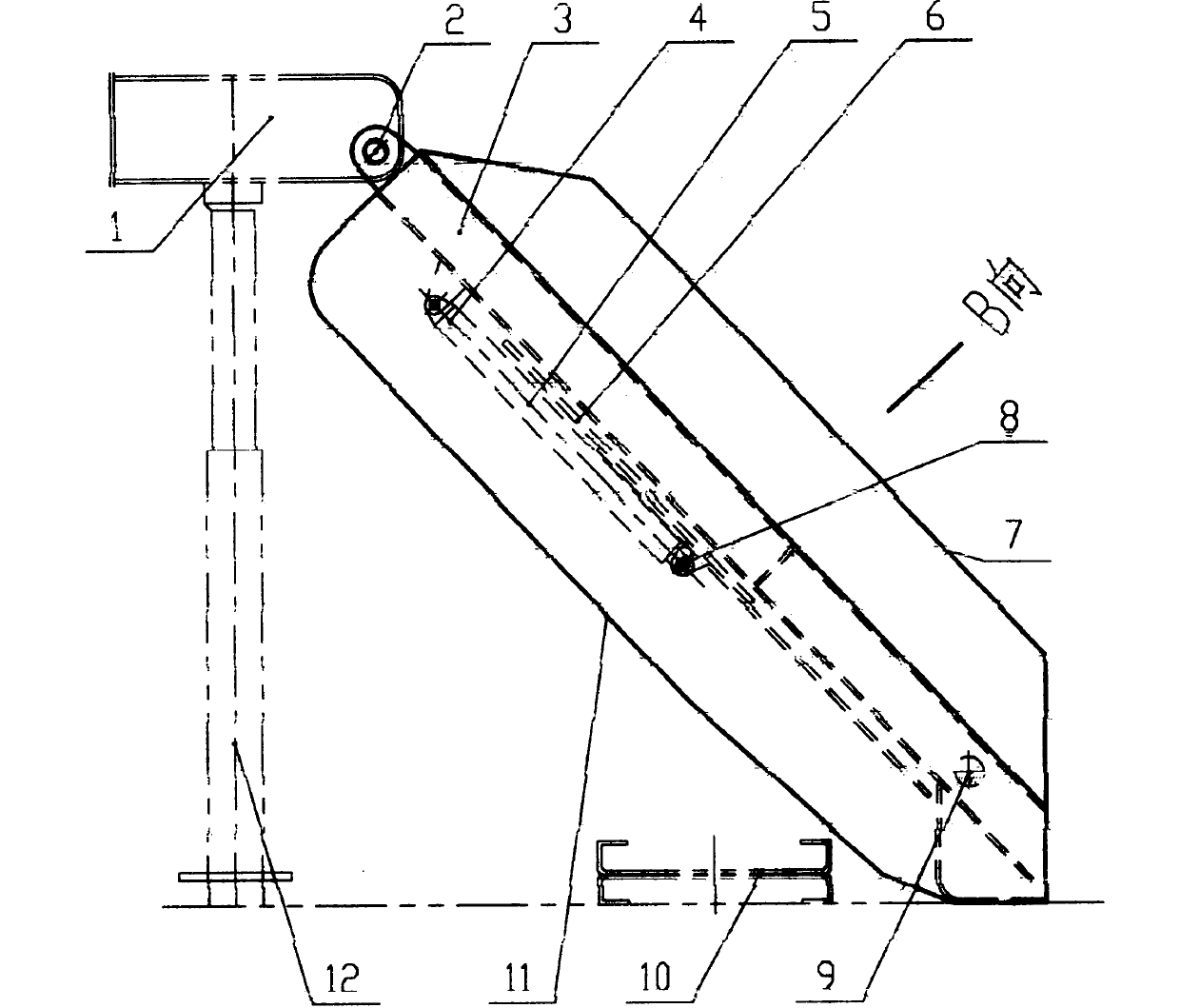
[0013] figure 1 Provided is a front view of a tail beam used for a hydraulic support of the present invention when the hydraulic support is installed together. Including the top beam 1, the hinge 2 located at the rear of the bracket and the upper part of the tail beam, the tail beam body 3, the coal discharge cylinder 5, the coal discharge gate 6, the hinge 4 connecting the coal discharge cylinder 5 and the tail beam body 3, and the coal discharge cylinder 5 and the hinge 8 of the coal discharge gate 6, the oil cylinder 9.

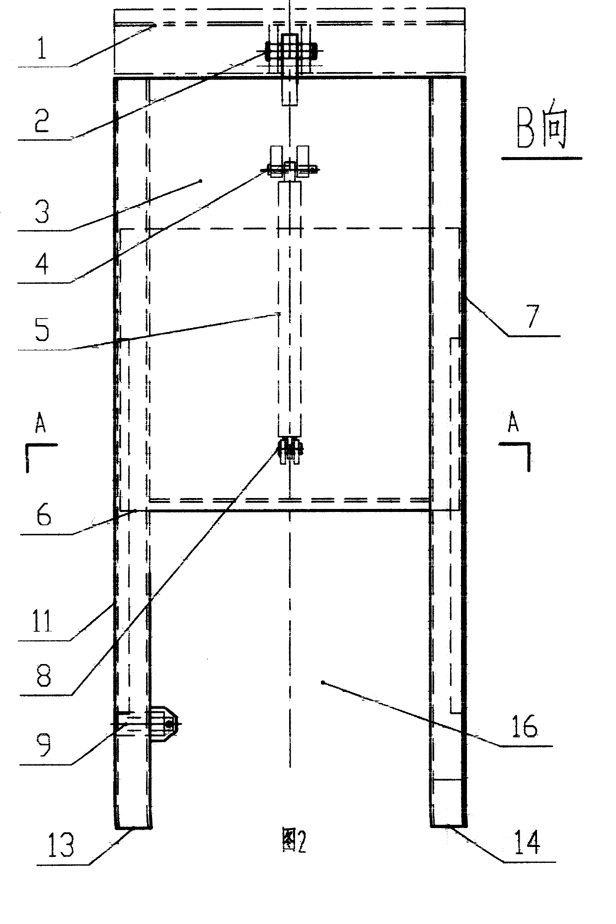
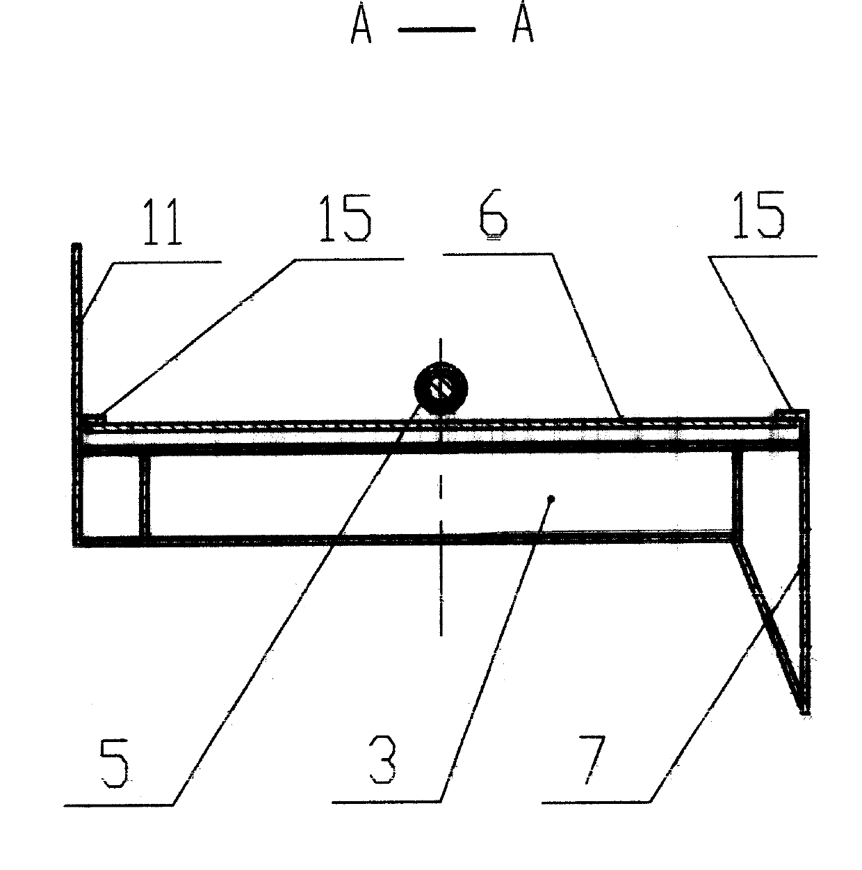
[0014] Combine below figure 1 , Figure 2 and image 3 Illustrate the action sequence of the tail beam used by a hydraulic support of the present invention when it is used in the coal mining face: when it is used in the working face, the tail beam used by a hydraulic support of the present invention is installed on the back of the top beam 1 through the only hinge 2, and its The lower end is supported on the base plate by bosses 13 and 14, and densely ar...


PUM


Abstract

The invention relates to a tail beam for a hydraulic bracket of a coal mine underground working face top slab shoring, which comprises a tail beam (3) with one end hinged on the tail of a bracket top beam (1) only by a hinged point (2) and the other end contacted with a soleplate by two lug bosses (13, 14), a top-coal caving strobe (6) which can slide along the tail beam (3), an oil cylinder (5) for driving the on-off of the strobe (6) and a direction-regulating oil cylinder (9). As the tail beam is only supported by three points of the hinged point (2), the lug boss (13) and the lug boss (14), the tail beam is stably supported and free from torsion, the weight is reduced. A recess between the lug bosses (13, 14) is convenient to discharge gangue and in particular suitable for being used in uneven soleplates and working faces with more dunn bass in coal wall.

Description

technical field [0001] The invention relates to a tail beam used for a hydraulic support of an underground working face of a coal mine. Background technique [0002] Hydraulic support is divided into two categories: fully mechanized mining support and sliding roof beam hydraulic support. The background technology of the present invention is the technology and the fully mechanized mining support described in the "General Technical Conditions for Sliding Roof Beam Hydraulic Support" of China's coal industry. Existing technologies in the field of sliding top beam hydraulic supports include suspended sliding top beam hydraulic supports (Chinese patent application No. 88104291.9); side-by-side sliding top beam hydraulic supports (Chinese patent application No. 91200747.8) and the like. The tail beams of the above-mentioned supports are mostly made of section steel, and there are straight tail beams, curved tail beams, zigzag tail beams, height-adjustable tail beams, and "banana"...

Claims


Application Information

Patent Timeline
Patent Type & Authority Patents(China)
IPC IPC(8): E21D23/04
Inventor 李泽宇
Owner 李泽宇
Why Eureka
Try Eureka