Engine crankcase oil gas separation system and its oil gas separation method

A separation system and oil-gas separator technology, applied in the field of automobile construction, can solve the problems of carbon deposition in the combustion system, poor oil-gas separation effect, poor oil-gas separation effect, etc., and achieve the effect of increasing the liquid content and improving the effect.

Inactive Publication Date: 2008-09-10
CHERY AUTOMOBILE CO LTD
View PDF0 Cites 20 Cited by
  • Summary
  • Abstract
  • Description
  • Claims
  • Application Information

AI Technical Summary

Problems solved by technology

[0003] However, in actual use, the oil-gas separation effect is often poor, which affects the normal operation of the engine.
[0004] General engine crankcase ventilation system, especially gasoline direct injection engine, the oil-gas separation effect is not good, causing oil to enter the intake system, and then enter the engine combustion system for combustion, resulting in poor combustion conditions, e...

Method used


Image

  • Engine crankcase oil gas separation system and its oil gas separation method

Examples


Embodiment 1

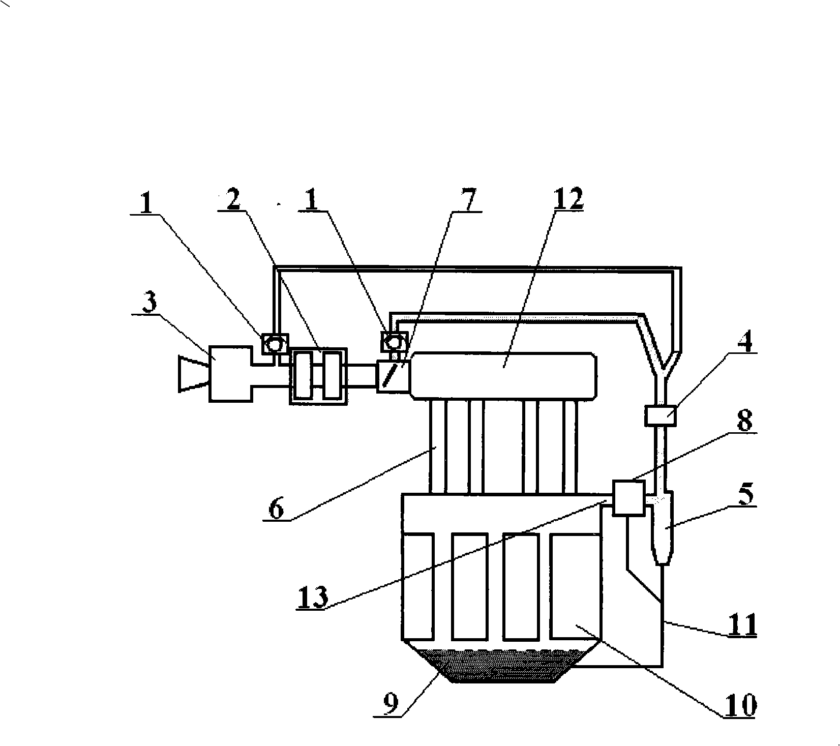
[0035] Described intercooler 8 is provided with oil return pipe 11, and this oil return pipe 11 communicates with the oil return pipe 11 of oil-gas separator 5 below intercooler, and leads into the oil sump of engine.

[0036] There is an oil return pipe 11 in the intercooler 8, and the oil gas cooled in the intercooler 8 returns to the crankcase through the oil return pipe 11.

[0037] According to the matching situation of the actual engine and the vehicle, the intercooler can be air-cooled or water-cooled. According to actual conditions, the intercooler 8 can be water-cooled or air-cooled. The following are specific examples of these two methods, and one application can be selected;

Embodiment 2

[0039] The cooling method of the intercooler 8 is a fan cooling type, that is, a cooling fan is arranged outside the shell of the intercooler 8, and the intercooler 8 is cooled by blowing or sucking air.

[0040] The fan cooling method has a relatively simple structure. It only needs to use a motor to drive the fan to rotate to cool down, but its cooling effect is not as good as that of the water cooling method. The fan is arranged in the direction of the air inlet, which is a blowing cooling method; the fan is arranged in the opposite direction of the air inlet, which is a suction cooling method.

Embodiment 3

[0042] The cooling method of the intercooler 8 is a cooling water cooling method, that is, inside the housing of the intercooler 8, a pipeline for cooling water is provided, and the cooling water therein circulates through an independently provided cooling system; The cooling system shared by the engines circulates.

[0043] The above-mentioned structure is relatively complicated, requiring the use of water pumps, pipelines, water tanks and various valves, and frequent replenishment of cooling water. But its cooling effect is very good. Because the cooling water pipeline can go deep into the inside of the intercooler 8 to take away its heat.


PUM


Abstract

The invention discloses an oil-gas separating system of an engine crankcase, which is arranged in a ventilation system of the engine crankcase and comprises an oil-gas separator (5) connected with an oil-gas outlet (13) of a crankcase; a gas outlet of the oil-gas separator (5) is communicated with a pipeline in a gas inlet end of a gas inlet main pipe (12); an intercooler (8) is arranged on a pipeline connected with the oil-gas outlet (13) of the crankcase and the oil-gas separator (5). The technical proposal is adopted on the basis of the ventilation system of the crankcase, the middle cooling part is arranged for cooling high-temperature mixed oil gas from the crankcase. With the temperature dropping, oil in the high-temperature mixed oil gas is changed from a gaseous state to a liquid state, thereby improving liquid content of the mixed oil gas. Part of the oil gas can be directly condensed and separated in the intercooler; liquid oil mist can be separated in the later oil-gas separation to improve the effect of the oil-gas separator.

Description

technical field [0001] The invention belongs to the technical field of automobile structure, and relates to the structure of automobile engines, including gasoline engines, especially in-cylinder direct injection gasoline engines and diesel engines. More specifically, the present invention relates to an engine crankcase oil and gas separation system. In addition, the present invention also relates to an oil-gas separation method adopted in the above-mentioned oil-gas separation system. Background technique [0002] At present, in the crankcase ventilation system of an automobile engine, the oil-gas separation method generally adopts a tornado-type oil-gas separator and a labyrinth oil-gas separator. The working principle of the tornado oil and gas separator is to form a certain air flow and use centrifugal force to separate the small oil droplets in the oil and gas. The working principle of the labyrinth oil and gas separator is to use a labyrinth to separate oil and gas. ...

Claims


Application Information

Patent Timeline
IPC IPC(8): F01M13/04
Inventor 魏建城
Owner CHERY AUTOMOBILE CO LTD
Why Eureka
Try Eureka