Illumination method using LED as illuminating source and illuminating apparatus

A technology of LED lighting and lighting devices, applied in lighting devices, components of lighting devices, light sources, etc., can solve the problems of being unable to adapt to the requirements of street lamp height and brightness changes, increasing LED distance, and increasing costs

Inactive Publication Date: 2008-09-10
欧阳杰 +1
View PDF0 Cites 4 Cited by
  • Summary
  • Abstract
  • Description
  • Claims
  • Application Information

AI Technical Summary

Problems solved by technology

However, the disadvantage of this street light is that each group of LEDs is still located on the same plate, and most of the light emitted by them will still intersect. If you do not want to make them intersect, you need to increase the distance between the LEDs; at the same time, there is a larger heat dissipation cover at the rear of the LEDs , so that the volume of the lighting device is relatively large; at the same time, due to the addition of lens covers with different angles on the LED, the structure of the lighting device becomes relatively complicated and the cost increases; moreover, because the lens cover added to the LED is fixed , which cannot adapt to the requirements of street lamp height and brightness changes

Method used


Image

  • Illumination method using LED as illuminating source and illuminating apparatus
  • Illumination method using LED as illuminating source and illuminating apparatus
  • Illumination method using LED as illuminating source and illuminating apparatus

Examples


Embodiment Construction
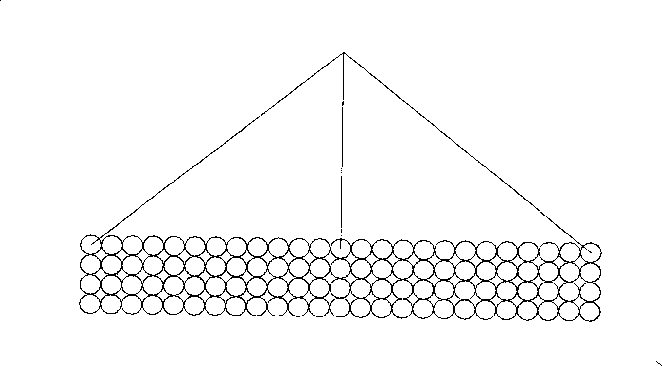
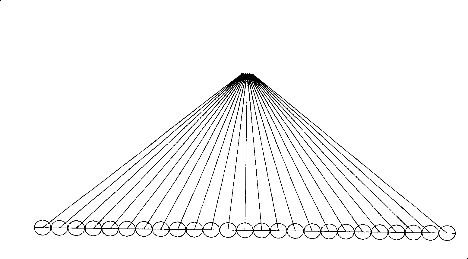
[0030] The idea of ​​the present invention is to divide the area to be illuminated first into lighting units according to the number of LEDs, and a convex lens is added in front of the LEDs to adjust the focus position of the LEDs so that the formed light spots fall in the corresponding partitions.

[0031] The present invention will be further described below in conjunction with accompanying drawing.

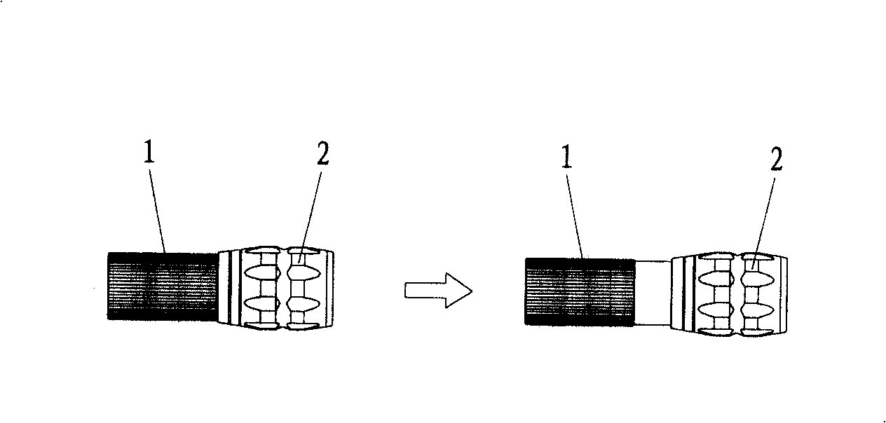
[0032] Such as figure 1 As shown, the LED and the convex lens are respectively placed in the tube body 1 and the tube body 2, and the tube body 1 and the tube body 2 are nested together and can slide relative to each other to realize the adjustment of the distance between the LED and the convex lens. When the distance between the tube body 1 and the tube body 2 is elongated, the light spot formed by the LED on the irradiated surface becomes smaller; when the distance between the tube body 1 and the tube body 2 decreases, the light spot formed by the LED on the irradiated surfac...


PUM


Abstract

The invention discloses an illumination method taking LEDs as a light source, wherein, the LEDs are intensively arranged on an LED fixing plate to form an array; each LED and the LED fixing plate form a certain setting angle so that the light emitted by the LED is shed to an illuminating unit corresponding to the LED; a convex lens is arranged in front of the LED; and the LED is positioned between single focus and twice focus of the convex lens; and the distance between the LED and the convex lens can be adjusted. After the proposal is adopted, because each LED is arranged according to different angles and forms correspondence to the illuminating unit on the illuminating side, the light emitted by each LED forms a condensed light spot instead of complete diverging light on the illuminating side, thereby the illuminating distance is long; the arranging intervals of the LEDs and the position of the convex lens are adjusted so that images of all LEDs on the illuminating side are closely arranged and distributed in the whole area; residual light on the edges of the LEDs is omitted so that the edge brightness of the illuminating side of an LED illumination device is high; therefore, the illumination of the whole LED illumination device is even and the range of the illuminating side is increased.

Description

technical field [0001] The invention relates to a lighting method and a lighting device, especially the lighting method and the device using LED as a light source. Background technique [0002] Traditional street lamps such as high-pressure mercury lamps are lighting products that rely on heat to emit light. They need to rely on external reflectors, such as reflectors, lampshades, etc. The waste of this light source can be as high as 40-60%. However, the performance of the LED light source can directly irradiate 80-90% of the luminosity on the target object, so under the same lumen value, the LED light source has a good advantage compared with other traditional light sources. LED lighting has become the mainstream of the era of green lighting and energy saving, and related applications are in the latest technologies and products such as street lights, decorative lighting, and night scene engineering. In view of this, the industry has developed LED street lamps. Due to the ...

Claims


Application Information

Patent Timeline
IPC IPC(8): F21S2/00F21V19/00F21V5/04F21V23/00F21V17/00F21W131/103F21Y101/02F21K9/00F21Y115/10
Inventor 欧阳杰欧阳伟
Owner 欧阳杰
Why Eureka
Try Eureka