Test bench wafer suction disc device

A suction cup, Taiwan crystal technology, applied in the field of test bench wafer suction cup devices, can solve the problems of increasing the test cost, increasing the wafer test time, etc., to reduce the test cost, fix and unload the wafer conveniently, and shorten the test time. Effect

Inactive Publication Date: 2008-09-10
无锡市易控系统工程有限公司
View PDF0 Cites 8 Cited by
  • Summary
  • Abstract
  • Description
  • Claims
  • Application Information

AI Technical Summary

Problems solved by technology

Such manual operation greatly increases the time of wafer testing, which will inevitably increase the cost of testing

Method used


Image

  • Test bench wafer suction disc device
  • Test bench wafer suction disc device

Examples


Embodiment Construction

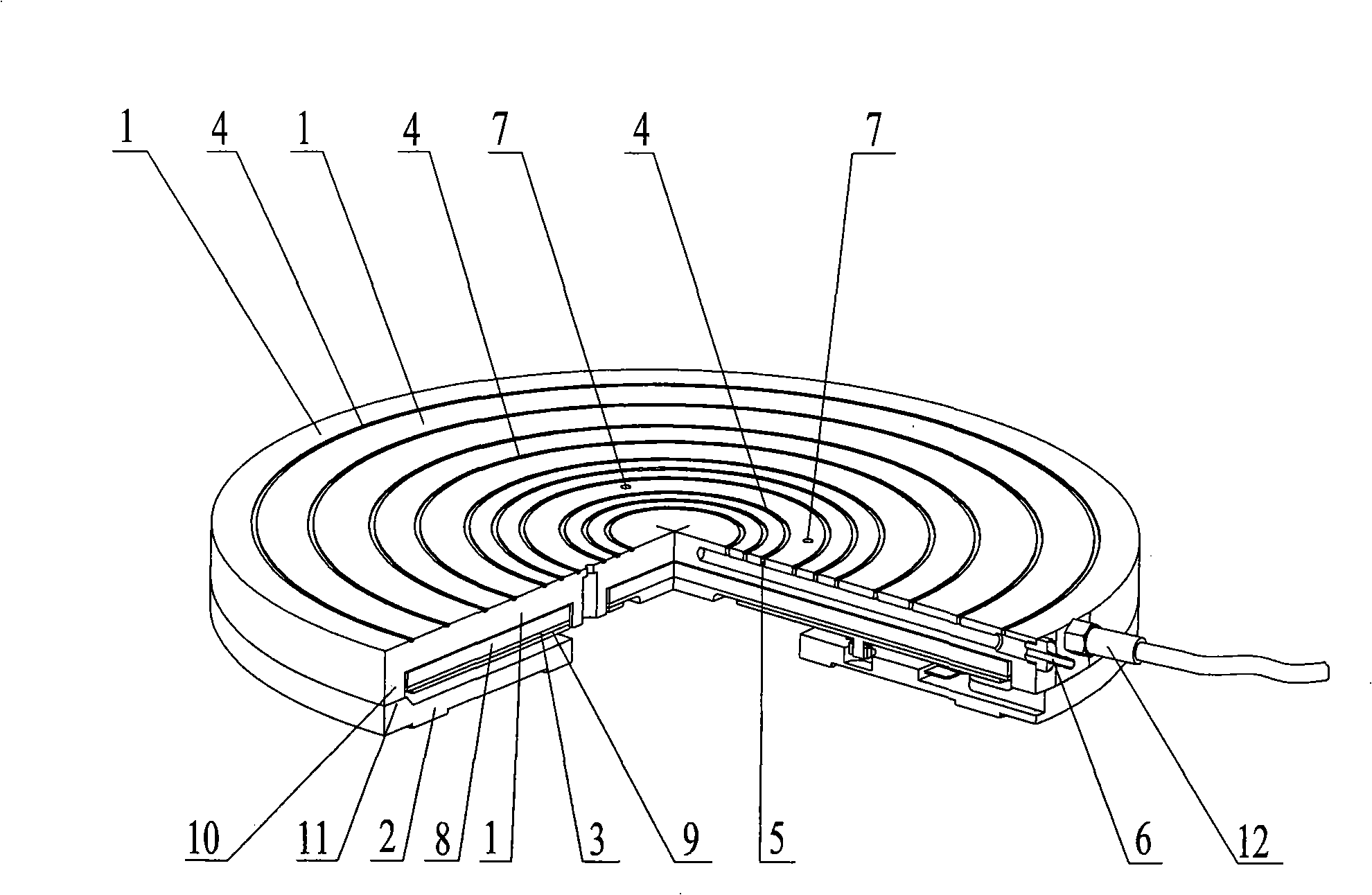
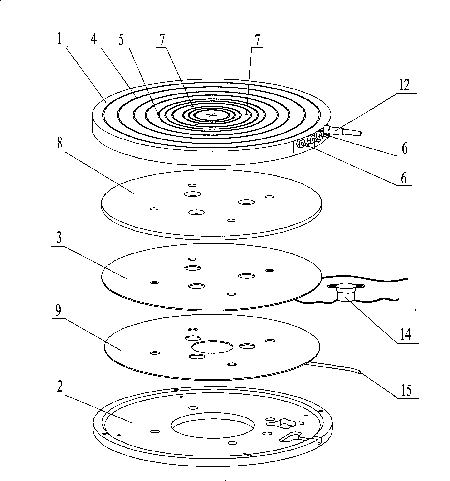
[0009] The present invention will be further described below in conjunction with specific drawings and embodiments.

[0010] As shown in the figure: the heater 3 arranged between the negative pressure suction cup 1 and the heat insulation disk 2 is provided with a number of negative pressure air grooves 4 on the upper surface of the negative pressure suction cup 1, and the negative pressure suction cup 1 is provided with a The negative pressure air hole 5 connected to the air groove 4 is provided with a negative pressure air pipe joint 6 on the negative pressure suction cup 1, and the negative pressure air pipe joint 6 communicates with the negative pressure air hole 5. The discharge hole 7 of the suction cup 1, the heater 3 and the insulation tray 2.

[0011] The negative pressure air groove 4 is a concentric circular groove formed on the upper surface of the negative pressure suction cup 1 . There are three or more discharge holes 7, which are evenly arranged between two ad...


PUM


Abstract

The invention relates to a detecting device for a wafer, in particular to a detecting wafer osculum device to fix the wafers in a vacuum adsorption way while being detected. According to the technical proposal provided by the invention, a heater is arranged between a subpressure sucker and an adiabatic tray; a plurality of subpressure air drains are arranged on the surface of the subpressure sucker; a subpressure pore communicated with the subpressure air drain is arranged inside the subpressure sucker and a subpressure gas-type fitting is arranged in the subpressure sucker, which is communicated with the subpressure pore; a discharge hole which runs through the subpressure sucker, the heater and the adiabatic tray are arranged in the subpressure sucker. While in use, the detecting device for a wafer is very convenient in fixing or unloading the wafer, which can greatly reduce detecting time, improve detecting sufficiency and effectively reduce detecting cost.

Description

technical field [0001] The invention relates to a wafer testing device, in particular to a wafer chucking device of a test bench for fixing the wafer during testing by means of negative pressure adsorption. Background technique [0002] At present, in the field of wafer testing, the testing machines and testing methods commonly used are manual testing or semi-automatic testing. Manual testing is to place each wafer manually, and use an optical microscope to align each die before manual testing, which is inefficient and makes the test accuracy lower; semi-automatic testing is to manually place the wafer on the test table, and then scan through the optical microscope , manually adjust the angle of the wafer and the position of the first die. Once adjusted, each die on the wafer is tested in turn. After testing each wafer, manually put the wafer back into the wafer cassette, and then take out the next wafer to repeat the above testing process. Such manual operation greatly i...

Claims


Application Information

Patent Timeline
Patent Type & Authority Applications(China)
IPC IPC(8): G01R1/02G01R31/26H01L21/66
Inventor 董晓清孙盘泉戴京东陈仲宇
Owner 无锡市易控系统工程有限公司
Why Eureka
Try Eureka