Artificial elbow joint

An elbow joint and artificial technology, applied in the field of semi-constrained artificial elbow joint, can solve problems such as unreliable screwing, and achieve the effects of shortening operation time, improving safety and easy assembly.

Inactive Publication Date: 2008-09-10
UNIV OKAYAMA +1
View PDF1 Cites 13 Cited by
  • Summary
  • Abstract
  • Description
  • Claims
  • Application Information

AI Technical Summary

Problems solved by technology

However, the possibility of unreliable screwing cannot be denied for an operator who has to perform such a complex procedure in a limited time

Method used


Image

  • Artificial elbow joint
  • Artificial elbow joint
  • Artificial elbow joint

Examples


Embodiment Construction

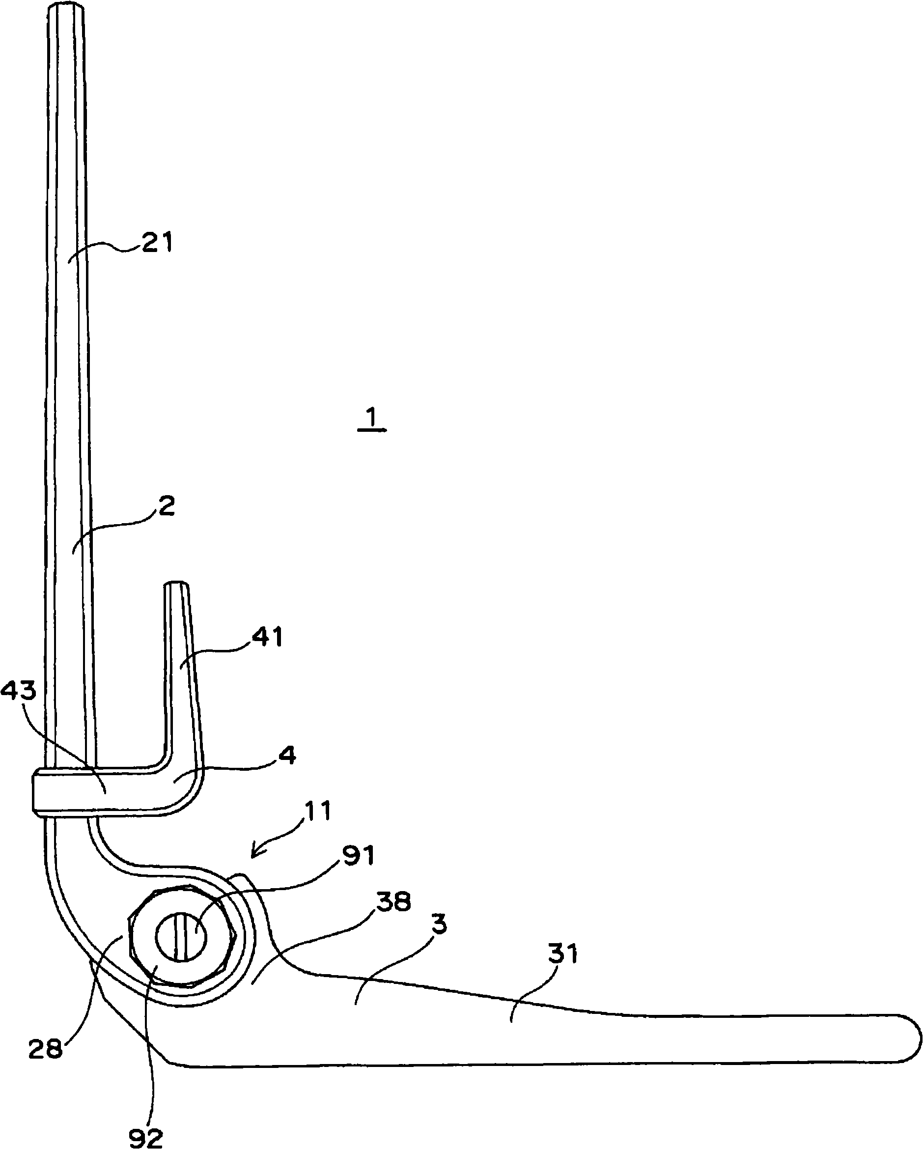
[0042] Artificial elbow joint of the present invention such as figure 1 As shown, the humeral component 2 and the ulna component 3 are connected by the joint part 11 .

[0043] figure 1 It is a diagram showing a state where the elbow joint is bent to approximately 90°, and the rod 21 of the humerus component 2 extends vertically, whereas the rod 31 of the ulna component 3 extends horizontally. The front flange 4 is mounted on the humerus rod 21 in such a manner as to be located inside the movable region of the elbow joint.

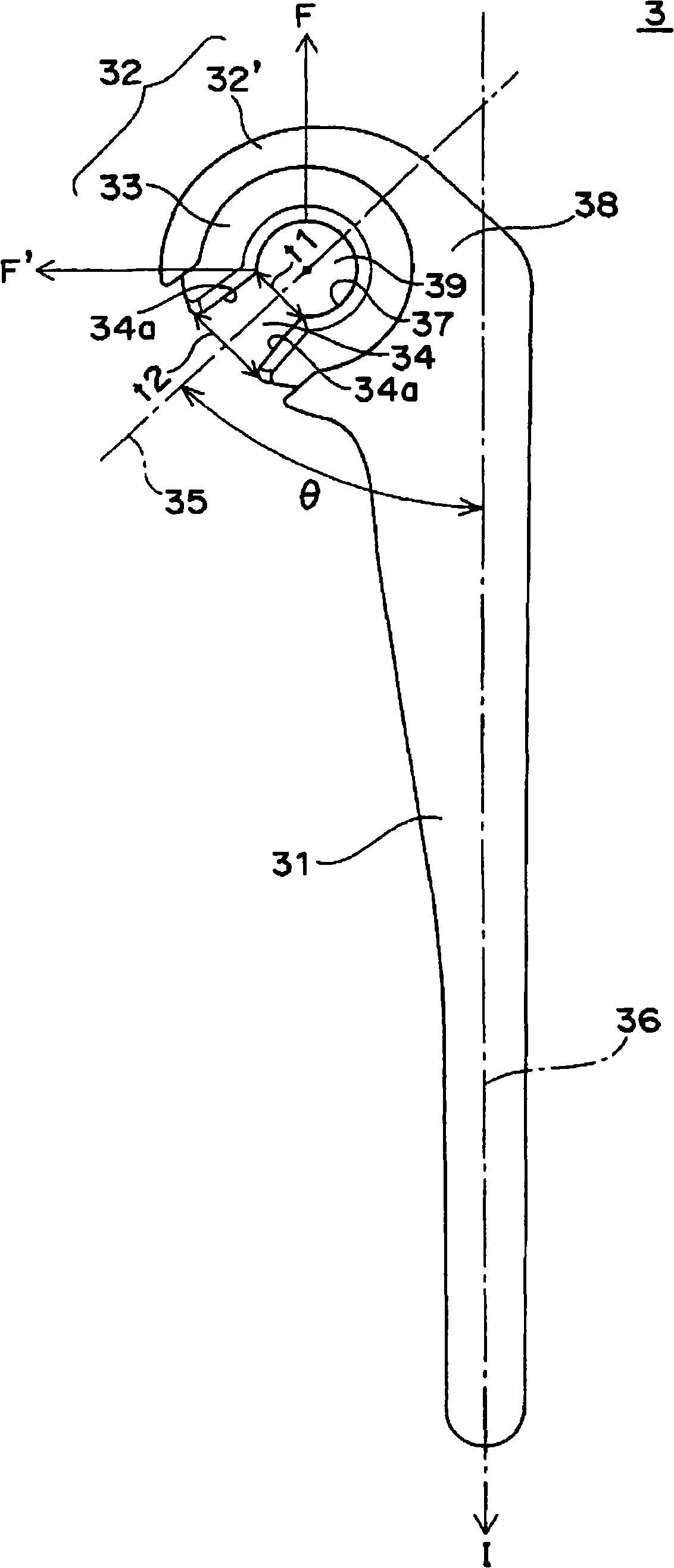
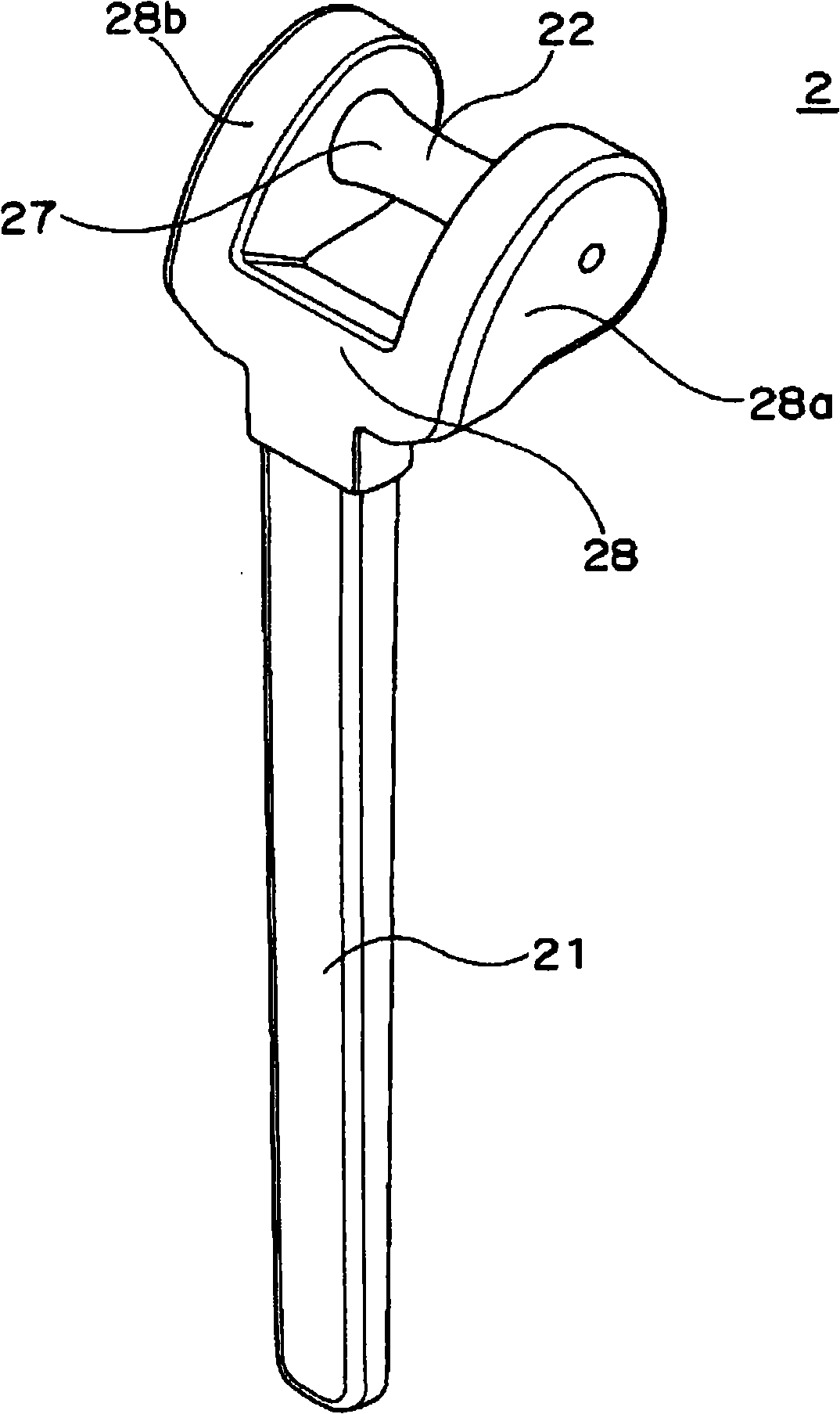
[0044] figure 2 and image 3 is a diagram showing the ulna component 3 and the humerus component 2 .

[0045] figure 2 The illustrated ulnar component 3 consists of an ulnar rod 31 for insertion into the bone marrow of the proximal part of the ulna and a sleeve portion 32 formed on the proximal side 38 of the rod 31 . The sleeve part 32 is made up of a sleeve shell part 32' made of a hard material and an embedded sleeve 33 made of a flexible part. ...


PUM


Abstract

The invention provides an artificial elbow joint of the constrain type by which a joint part can be easily fabricated even in the course of a surgical operation for replacing the joint elbow and which is therefore effective in improving the safety of the operation and shortening the operation time. This artificial elbow joint as described above is composed of a humeral component involving a humeral stem, a shaft part and an anterior frange and an ulnar component involving an ulnar stem and a sleeve part. In this artificial elbow joint, the shaft part of the humeral component and the sleep part of the ulnar component join together in a revolvable manner. This artificial elbow joint is characterized in that the sleeve part has a sleeve opening, which is in the shape of a slit narrower than the outer diameter of the shaft part, and a flexible sleeve insert located in the inner face of the sleeve being in contact with the shaft part so that the sleeve part can undergo snap-in joint to the shaft part from the sleeve opening, while the angle of the opening center line of the sleeve opening is within a range of from 45 DEG to 90 DEG from the bottom of the main axis of the ulnar stem toward the inner direction of the elbow.

Description

technical field [0001] The invention relates to an artificial elbow joint used in elbow joint replacement surgery, in particular to a semi-constrained artificial elbow joint. Background technique [0002] When the elbow joint is damaged due to rheumatism, osteoarthritis, or trauma, the function of the elbow joint is lost and severe pain is felt at the same time. In such cases, an artificial elbow replacement surgery is required in order to restore the function of the elbow joint. [0003] The artificial elbow joint has a humeral component fixed on the distal part of the humerus and an ulnar component fixed on the proximal part of the ulna, and the ends of these components move in coordination to form the joint part. According to the shape of the joint part, artificial elbow joints can be roughly divided into two types. One type is called the semi-constrained type, which is an artificial elbow joint in which the humeral component and the ulnar component are mechanically con...

Claims


Application Information

Patent Timeline
Patent Type & Authority Applications(China)
IPC IPC(8): A61F2/38
CPCA61F2/3804A61F2002/3813A61F2310/00023A61F2310/00029
Inventor 西田圭一郎井上一横川道博
Owner UNIV OKAYAMA
Why Eureka
Try Eureka