

Casting method
A casting method and casting mold technology, which is applied in the direction of casting molding equipment, casting molds, casting mold components, etc., can solve the problems of complicated follow-up processes such as parting and product separation, which have not been disclosed or implemented, and low injection qualification rates
- Summary
- Abstract
- Description
- Claims
- Application Information
AI Technical Summary
Problems solved by technology
Method used
Image

Examples
Embodiment 1
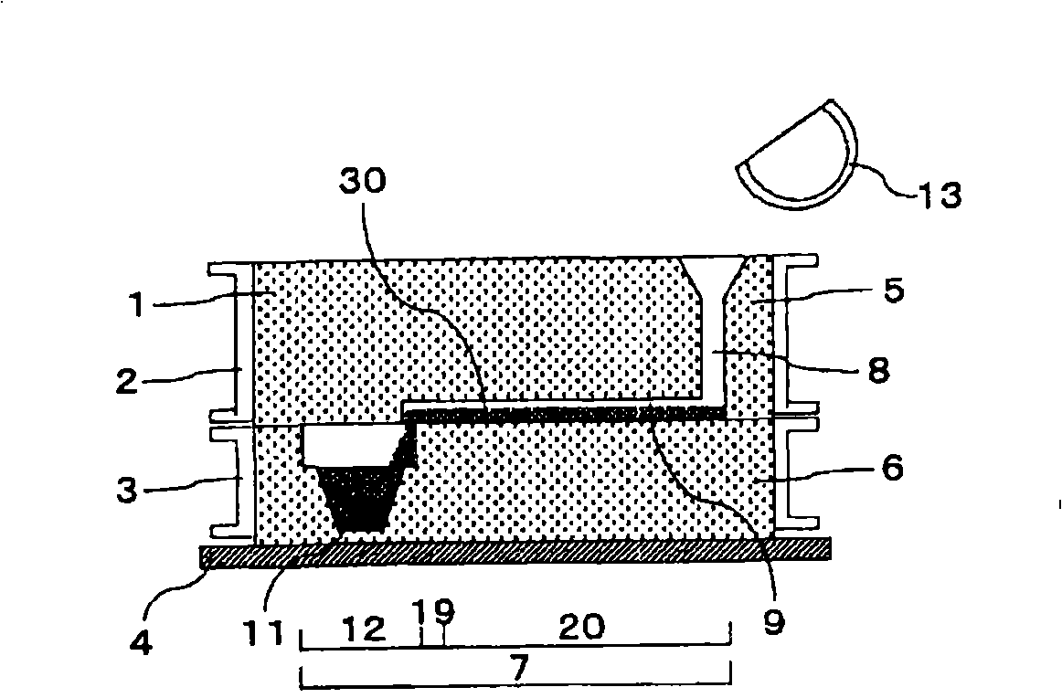
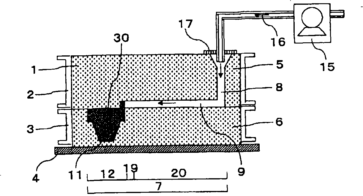
[0142] figure 1 and figure 2 Example 1 is shown. For method 1 in this example, start pouring molten metal approximately equal to the volume of the desired cavity portion to be filled with molten metal into the cavity of the air-permeable mold, and then send compressed gas from the gate. A casting method in which molten metal is filled into a desired cavity and solidified will be described.
[0143] Firstly, the structure of the casting mold 1 will be described. The casting mold 1 is a sand mold, which is molded in the upper frame 2 and the lower frame 3, and placed on the mold base 4 after the molds are closed. The mold cavity 7 is composed of a gate part 8 , a runner part 9 and a product part 11 . Generally, a riser portion is often provided between the runner portion 9 and the product portion 11 , but this case is a case of a mold without a riser portion.
[0144] In this embodiment, a casting method will be described in which only the product part 11 itself, which is t...
Embodiment 2
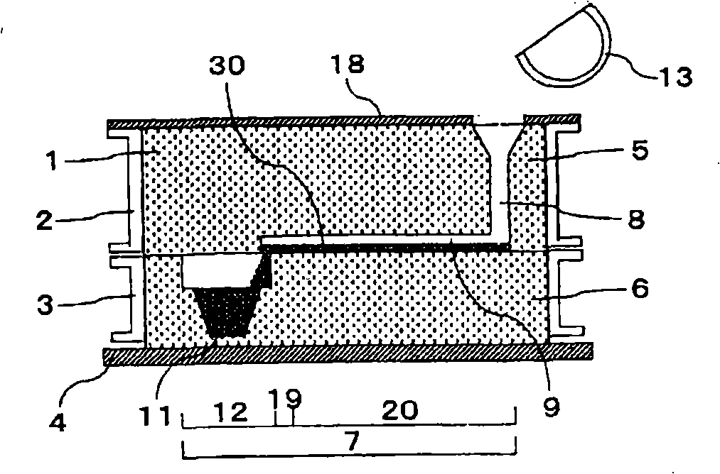
[0154] image 3 and Figure 4 Example 2 is shown. In this example, method 2 is used to describe a casting method in which a compressed gas is fed to fill a desired cavity portion with molten metal after pouring starts, and the molten metal is solidified while the compressed gas is fed.
[0155] image 3 The state after pouring the molten metal 30 into the product part 11 which is the desired cavity part 12 is shown. The configuration of the mold 1 and the cavity 7 is the same as that of the first embodiment, and an iron cover member 18 is placed on the upper part of the upper frame 2 for airtightness. The covering member 18 is provided to make the pressure of the compressed gas more effective. The cover member 18 is preferably made of a non-ventilated material, but the same effect can be obtained with a material having less air permeability than the mold.
[0156] image 3 The state after pouring is the same as that shown in Example 1, the pouring amount is only the prod...
Embodiment 3
[0162] Figure 5 and Figure 6 Example 3 is shown. In this embodiment, using method 3, a part of the desired cavity portion to be filled is located in the upper mold, and in the case of a certain height, the pressurization pressure of the compressed gas is clearly specified, and the molten metal is filled to the desired Desired cavity parts and solidified casting methods are described.
[0163] Such as Figure 5 As shown, the composition of the casting mold 1 is substantially the same as that of the embodiment 2, and the casting mold cavity 7 is composed of a gate part 8 , a runner part 9 , a riser part 10 and a product part 11 . In addition, the product part 11 is arranged in the upper mold 5 and the lower mold 6 and the height of the upper mold part is H. In the present embodiment, the product part 11 and the riser part 10 are filled with molten metal as the desired cavity part 12 and solidified. The aforementioned height H corresponds to the height of the molten metal ...
PUM
 Abstract
Description
Claims
Application Information