High pressure discharge lamp with discharge chamber

A technology of high-pressure discharge lamps and discharge tubes, which is applied in high-pressure discharge lamps, discharge lamps, gas discharge lamps, etc., can solve the problems of shortened lifespan, and achieve the effect of optimizing the electrode geometry and effectively coupling the heating process

Inactive Publication Date: 2008-09-10
PATENT TREUHAND GESELLSCHAFT FUR ELECTRIC GLUEHLAMPEN MBH
View PDF2 Cites 2 Cited by
  • Summary
  • Abstract
  • Description
  • Claims
  • Application Information

AI Technical Summary

Problems solved by technology

If things are indeed being made darker, it is to a very limited extent and possibly at the cost of reduced lifespan

Method used


Image

  • High pressure discharge lamp with discharge chamber
  • High pressure discharge lamp with discharge chamber
  • High pressure discharge lamp with discharge chamber

Examples


Embodiment Construction

[0020] The principle circuit of an electronic ballast for high-pressure discharge lamps is based eg on page 217 of Sturm Figure 4 .44 implementation form.

[0021] The working method can use bipolar rectangular wave supply current. Such a supply current is characterized, for example, by a short-term residual power for stable rectification. The power obtained therein corresponds to the rated power of the lamp and is lower than the rated power in the dimmed situation.

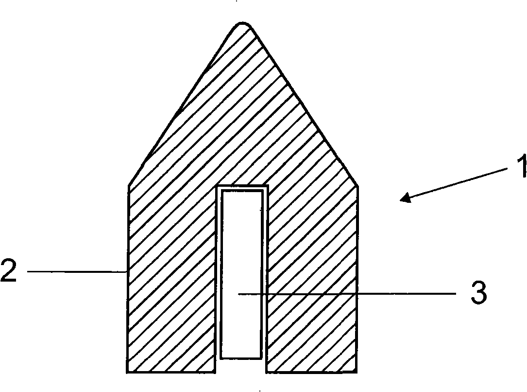
[0022] figure 1 A suitable electrode 1 for a metal halide lamp is shown in , where heating is effected by a heating core 3 placed in the head 2 of the electrode. In this case, the contacts of the heater of the core can be connected to the electrodes.

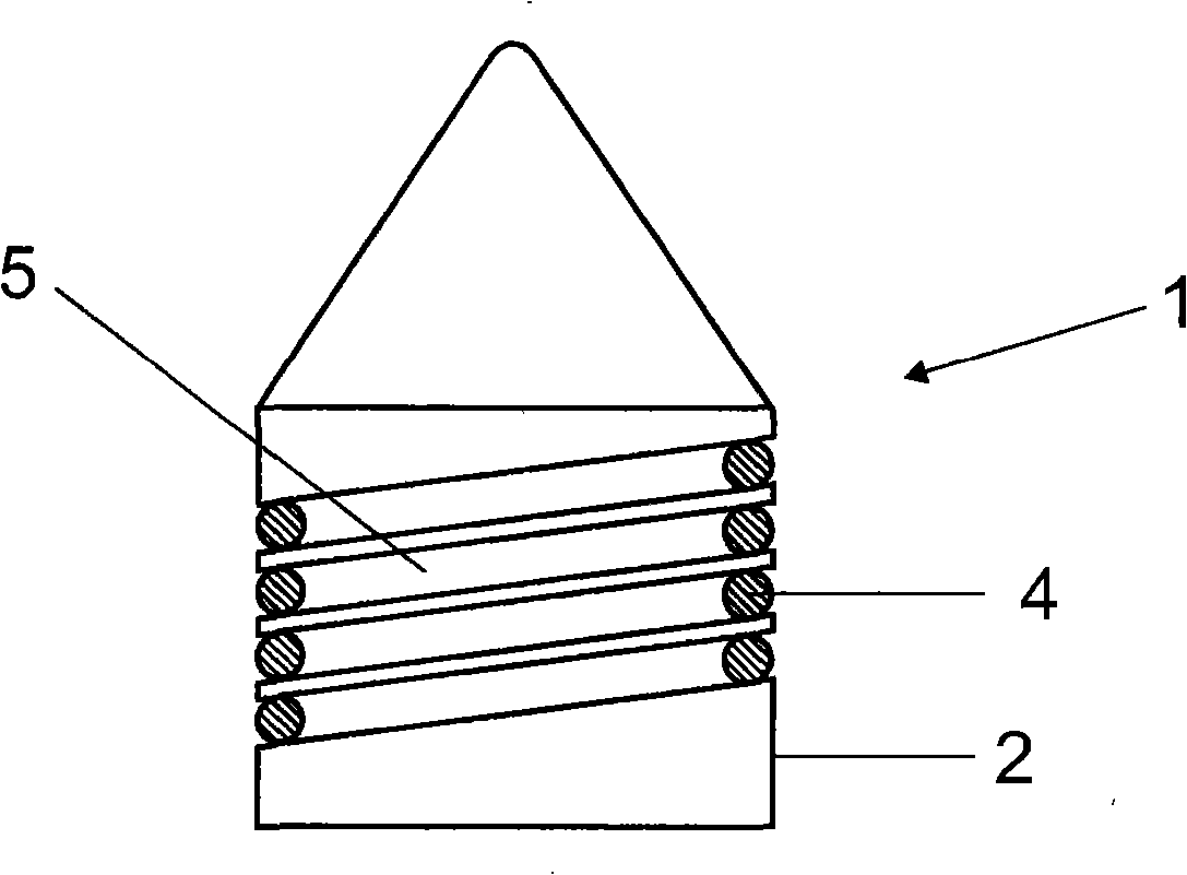
[0023] figure 2 The head 2 of the electrode 1 is shown in , wherein the heating means in the form of a wire 4 is embedded in a thread-like groove 5 of the head 2 . The contacts can still be connected to the electrodes.

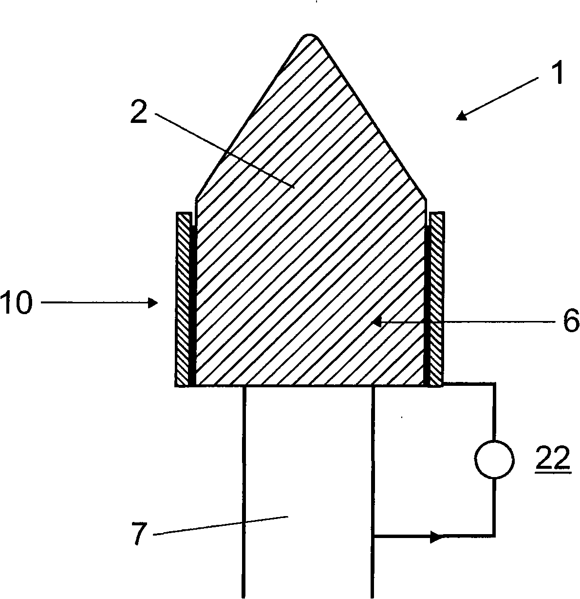
[0024] exist image 3 In , the hea...


PUM


Abstract

The invention relates to an electrode (1) of a high pressure discharge lamp with a heating device (3) housed in the head (2) in order to compensate for problems in dimmed operation.

Description

technical field [0001] The invention is based on a high-pressure discharge lamp with a ceramic discharge vessel according to the preamble of claim 1 . These are in particular metal halide lamps, in particular metal halide lamps for general lighting, or also high pressure sodium lamps. Background technique [0002] DE-A 10 2004 020 397 discloses a method for dimming a high-pressure discharge lamp. [0003] Various possibilities for dimming high-pressure discharge lamps are also disclosed in the book Betriebsgeraete und Schal tungen fuer elektrische Lampen, C.H.Sturm und E.Klein, 1992, SAG (hereinafter referred to as Sturm), see in particular pages 235 and 296- 297 pages. The problem, however, is that in the event of a reduced input power, the electrodes and possibly also the discharge vessel cool down. For these reasons, dimming high-pressure discharge lamps has hitherto not been widely used. If the situation is indeed being dimmed, it is also to a very limited extent and...

Claims


Application Information

Patent Timeline
Patent Type & Authority Applications(China)
IPC IPC(8): H01J61/073H01J61/52H01J61/86
CPCH01J61/526H01J61/82H01J61/0732H01J61/073H01J61/52H01J61/86
Inventor 戈特哈德·施莱歇
Owner PATENT TREUHAND GESELLSCHAFT FUR ELECTRIC GLUEHLAMPEN MBH
Why Eureka
Try Eureka