
Series changing multi-stage rolling machine

A rolling mill and series technology, applied in the direction of metal rolling stand, metal rolling mill stand, roll, etc., can solve the problems of complex structure, small support work roll, and reduced ability to control the shape of the plate

Active Publication Date: 2010-09-01
IHI CORP
View PDF8 Cites 0 Cited by
  • Summary
  • Abstract
  • Description
  • Claims
  • Application Information

AI Technical Summary

Problems solved by technology

[0007] However, in the technique disclosed in Patent Document 1, when the diameter of the work rolls is small and the number of stages is large, it is necessary to separately arrange the headstocks supporting the work rolls and the shafts supporting the intermediate rolls in a limited space (frame). box, so the axleboxes (bearings) that support the work rolls become smaller
Therefore, the rolling load (thrust load) and bending load cannot be increased, so there is a problem that the ability to control the shape of the strip during rolling is reduced.
[0008] In addition, when replacing the work rolls and the intermediate rolls, there is a problem that the headboxes do not interfere with each other, so that the structure becomes complicated.
In addition, there is a problem that the intermediate roll and the like must be disassembled even when only the work roll is replaced.

Method used


Image

  • Series changing multi-stage rolling machine
  • Series changing multi-stage rolling machine
  • Series changing multi-stage rolling machine

Examples


Embodiment Construction

[0037] Next, embodiments of the stage switching multi-stage rolling mill of the present invention will be described with reference to the drawings.

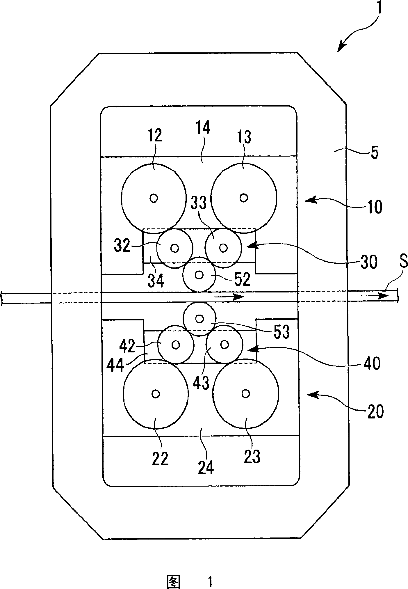
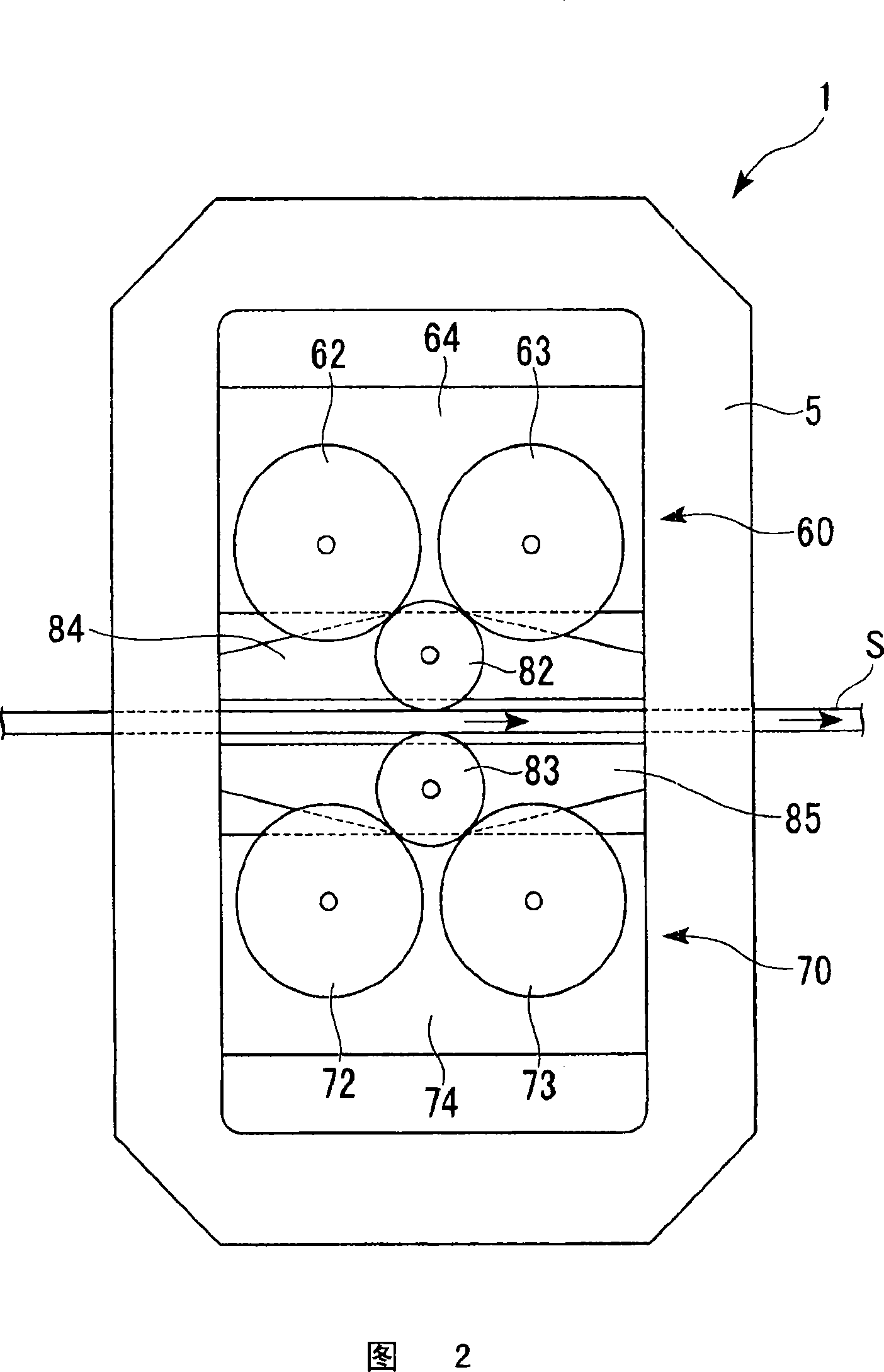
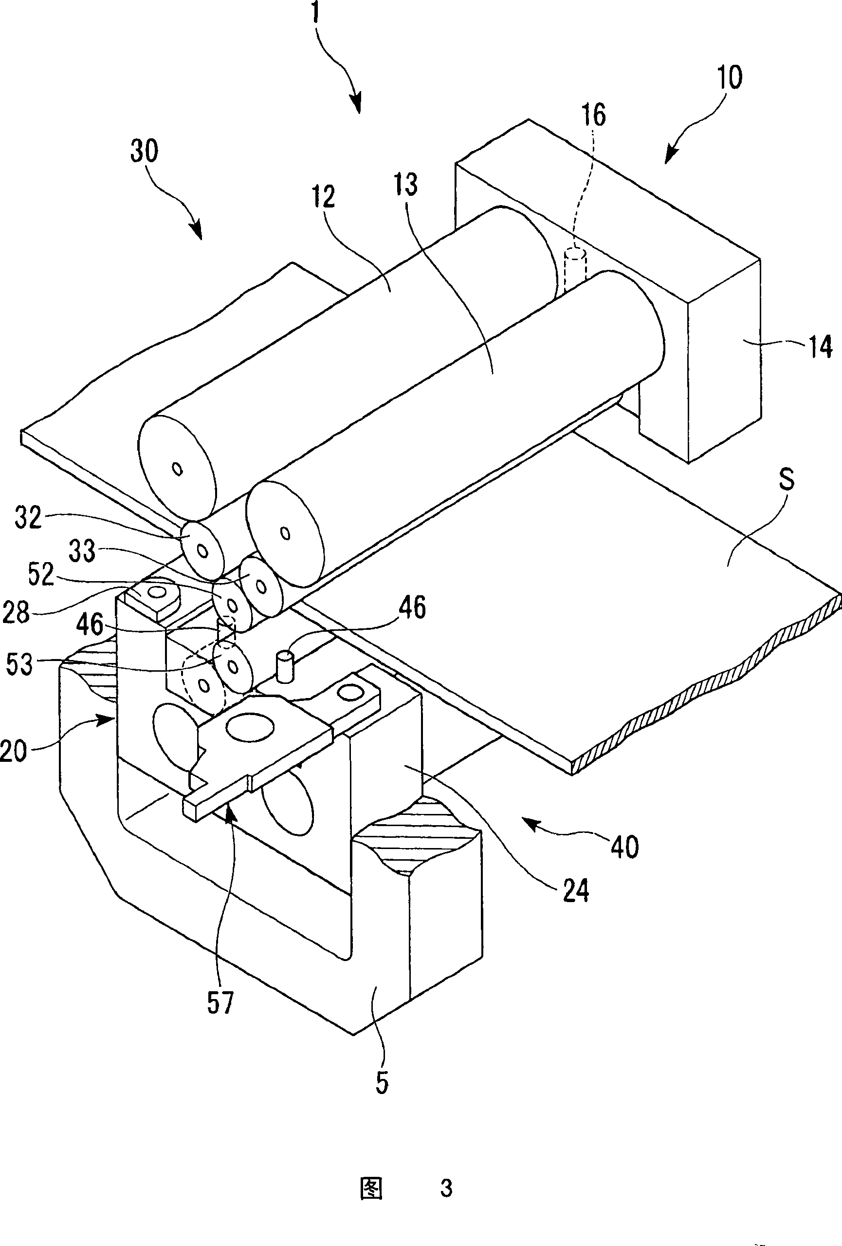
[0038] figure 1 It is a side view schematically showing the stage switching multi-stage rolling mill 1 in a 10-stage configuration. figure 2 It is a side view schematically showing the stage switching multi-stage rolling mill 1 in a six-stage configuration. image 3 It is a perspective cross-sectional view showing the stage number switching multi-stage rolling mill 1 in a 10-stage configuration.

[0039] The number of stages switching multi-stage rolling mill 1 can be switched to a structure in which the diameters of the work rolls 52, 53 are small and the number of stages is large (10 stages) as required (refer to figure 1 ), and work rolls 82, 83 with large diameters and few stages (6 stages) (refer to figure 2 ) multi-stage rolling mill.

[0040] Such as figure 1As shown, in the case of a 10-stage structure, the stage s...


PUM


Abstract

The invention relates to a series handover multistage rolling machine, including a first working roller, a second working roller, a first support roller group, a second support roller group and two roller-type bearings. The first working roller is configured at one surface side of a supplied workpiece to contact with a surface of the workpiece. The second working roller is configured at another surface side of the workpiece in a way of being parallel to the first working roller to contact with another surface of the workpiece. The first support roller group is configured at one surface side of the workpiece in a mutually parallel way and formed by being driven by a plurality of support rollers of the first working roller directly or indirectly. The second support roller group is configured at another surface side of the workpiece in a mutually parallel way and formed by being driven by a plurality of support rollers of the second working roller directly or indirectly. The two roller-type bearings are respectively configured at two ends of the first working roller and the second working roller and contacted with two end surfaces of the first working roller and the second working roller separately, and the two roller-type bearings are permitted to rotate in the mutually opposite directions of each working roller and support each working roller in a pushing direction.

Description

technical field [0001] The invention relates to a series switching multi-stage rolling mill. [0002] This application claims priority based on Japanese Patent Application No. 2007-64689 filed on March 14, 2007, the contents of which are incorporated herein by reference. Background technique [0003] In order to improve the shape control and rolling ratio of rolled materials, various multi-stage rolling mills (X-type mills) in which upper and lower work rolls are supported by two backup rolls have been proposed. [0004] In a multi-stage rolling mill, the smaller the diameter of the work roll and the more stages, the higher the rolling rate and the high rolling load for hard materials can be obtained, but the rolling stability, rolling speed and The appearance (shape and surface roughness) of rolling is reduced. And conversely, the larger the diameter of the work roll and the fewer the number of stages, the better the rolling stability, rolling speed and appearance of the ...

Claims


Application Information

Patent Timeline
Patent Type & Authority Patents(China)
IPC IPC(8): B21B29/00B21B31/07B21B27/10B21B31/08B21B13/14B21B13/00B21B31/16
CPCB21B13/02B21B13/04B21B27/06B21B27/10B21B31/07B21B31/08
Inventor 本城恒松泽司都筑茂
Owner IHI CORP
Learn More