Hot air engine

A hot air engine and cylinder technology, which is applied to hot air variable capacity engine devices, mechanical equipment, machines/engines, etc., can solve the problems of increased friction between the valve piston and the cylinder wall, wear, and difficulty in sealing.

Inactive Publication Date: 2008-09-17
黄元卓
View PDF2 Cites 5 Cited by
  • Summary
  • Abstract
  • Description
  • Claims
  • Application Information

AI Technical Summary

Problems solved by technology

[0002] Most of the traditional heat engines use an inertial system to drive the piston movement through the double-ring mechanism or the crankshaft mechanism to complete the thermodynamic cycle (CN1217765A). The disadvantage is that the actual working cycle is difficult to approach the theoretical cycle, and it needs to be operated under high temperature and high pressure conditions. This again brings the problem of sealing difficulties
CN2315306Y discloses a scheme for driving the movement of the gas distribution piston by an elastic turning mechanism, so that the actual working cycle is closer to the theoretical cycle, but the actual cycle is affected by the spring parameters, which is difficult to adjust, and the lateral force is difficult to balance, especially When the piston is in the spring flip position, the friction between the gas distribution piston and the cylinder wall will increase due to the large lateral force, which will affect the movement of the piston and increase the wear due to friction

Method used


Image

  • Hot air engine
  • Hot air engine
  • Hot air engine

Examples


Embodiment Construction

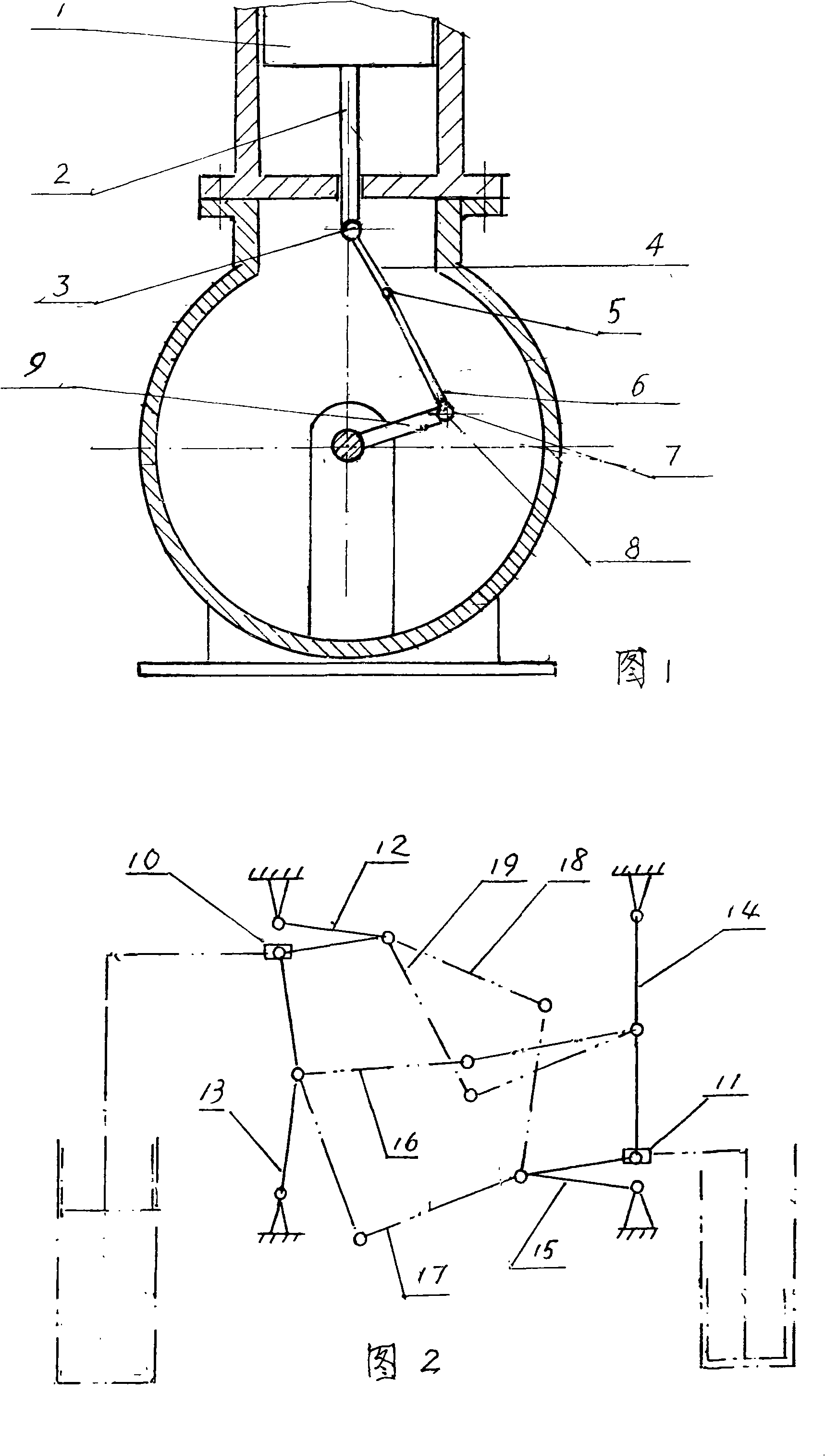
[0018] Further description will be made below in conjunction with the embodiments. Fig. 1 is a schematic diagram of the connection of the piston, the two connecting rods and the crankshaft. The piston of the double-acting heat engine and the power piston of the gas distribution type heat engine are all connected by this connection. The guide rod 2 of the piston 1 is connected with the connecting rod 4 through the hinge 3, and the latter is hinged with the connecting rod 6 through the hinge 5. The connecting rod 6 is connected with the connecting rod journal 8 of the crankshaft through the bearing 7. The length of the crank 9 of the crankshaft is the radius of rotation of the journal 8. The principle for determining the length of each rod is: when the piston is at the highest point, that is, when the journal 8 is at the highest point, its The axis is used as the starting point of 0 degrees. When the journal 8 is at the 180-degree position and the second connecting rod is straigh...


PUM


Abstract

A heat engine consists of one to four groups of cylinder bodies and corresponding pistons, a crank shaft, a heater, a regenerator and a cooler, which can be of gas distribution type or of double acting type, wherein, the piston and the crank shaft inside the cylinder body are a two-link and combined locking-releasing mechanism; the clearance between the piston and the sidewall of the cylinder body is provided with pressure gas for forming a thin gas layer, thus being easy to work in relatively low thermal parameters.

Description

[0001] The invention relates to a heat engine, in particular to a heat engine whose piston and crankshaft are connected by two connecting rods and a lock-release mechanism. Background technique: [0002] Most of the traditional heat engines use an inertial system to drive the piston movement through the double-ring mechanism or the crankshaft mechanism to complete the thermodynamic cycle (CN1217765A). The disadvantage is that the actual working cycle is difficult to approach the theoretical cycle, and it needs to be operated under high temperature and high pressure conditions. This again brings about the problem of difficult sealing. CN2315306Y discloses a scheme for driving the movement of the gas distribution piston by an elastic turning mechanism, so that the actual working cycle is closer to the theoretical cycle, but the actual cycle is affected by the spring parameters, which is difficult to adjust, and the lateral force is difficult to balance, especially When the pisto...

Claims


Application Information

Patent Timeline
Patent Type & Authority Applications(China)
IPC IPC(8): F02G1/043F02G1/053
Inventor 黄元卓
Owner 黄元卓
Why Eureka
Try Eureka