Resistance balance circuit

A technology of balancing circuits and resistances, applied in circuit layout, electric light sources, electrical components, etc., to achieve the effect of equalizing the on-current and solving uneven brightness

Active Publication Date: 2011-07-06
IND TECH RES INST
View PDF1 Cites 0 Cited by
  • Summary
  • Abstract
  • Description
  • Claims
  • Application Information

AI Technical Summary

Problems solved by technology

However, in order to achieve the uniformity of conduction current, multiple parallel LEDs 140 in the LED package 14 are adjacently arranged, so it is not easy to dissipate heat, and the red, green, and blue color mixing results are easily affected because the multiple LEDs 140 are in parallel structure; , the LED array 15 formed by connecting multiple LED packages 14 in series also has the aforementioned Figure 1 shows the circuit resistance imbalance problem of the LED array structure
[0006] Therefore, how to solve the problem of uneven brightness caused by the unbalanced line resistance of the existing LED array structure, and at the same time overcome the problems of high cost and complicated manufacturing process (process) The problem is actually an urgent problem to be solved when using the LED array structure as the light source equipment

Method used


Image

  • Resistance balance circuit
  • Resistance balance circuit
  • Resistance balance circuit

Examples


Embodiment Construction

[0047] The implementation of the present invention is described below through specific examples, and those skilled in the art can easily understand other advantages and effects of the present invention from the content disclosed in this specification.

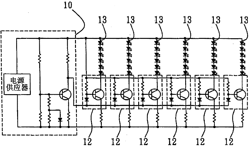
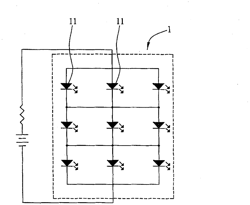
[0048] Such as Figure 4A As shown, it is a schematic diagram of the circuit structure used to illustrate the first embodiment of the resistance balancing circuit of the present invention, and Figure 4B As shown, it is a schematic diagram of the circuit structure used to illustrate the second embodiment of the resistance balancing circuit of the present invention, and Figure 4B is concatenation of multiple groups such as Figure 4A A schematic diagram of the circuit architecture of the resistor balancing circuit shown. The resistance balancing circuit of this embodiment is applied to at least two electronic components arranged in a column matrix, so that the line resistance (ie, the line resistance) of the circuit through w...


PUM


Abstract

A resistor balancing circuit is provided with at least two electronic element which are arrayed in a row matrix, and are connected in parallel to form a row matrix structure; an input end provided at one end of the row matrix structure for providing a conducting current for each electronic element in the row matrix structure; and an output end which is arranged on the row matrix structure catercorner with the input end for educing the conducting current for each electronic element in the row matrix structure, wherein, the length of the conducting current, which passes through each electronic element, from the input end to the output end is equal to each other. Because in the resistor balancing circuit of the invention, the input end for providing the conducting current for each electronicelement in the matrix array structure and the output end for educing the conducting current for each electronic element in the matrix array structure are catercorner arranged, the length of the conducting current, which passes through each electronic element, from the input end to the output end is equal to each other, further, electronic elements mounted on each branch of the matrix array structure acquires same conducting current.

Description

technical field [0001] The present invention relates to a resistance balancing circuit, in particular to a resistance that is arranged in a row matrix or a column matrix as a connection structure for electrically connecting at least two electronic components to ensure the uniformity of the conduction current flowing through the electronic components balanced circuit. Background technique [0002] Because light emitting diodes (Light Emitting Diode; LED) have the advantages of high efficiency, long life, and unbreakable advantages that cannot be compared with traditional light sources, they are widely used, such as traffic lights, car lights, table lamps, street lights, billboards and LCD LEDs can be seen in light source equipment such as display backlight modules. [0003] The light source equipment using LED as lighting needs to use a large number of LEDs, thus forming such as figure 1 The LED array structure 1 shown, but due to the difference in the characteristics of ...

Claims


Application Information

Patent Timeline
Patent Type & Authority Patents(China)
IPC IPC(8): H05B33/08F21V23/00F21Y101/02H05B44/00F21Y115/10
Inventor 黄添富胡国昌花士豪
Owner IND TECH RES INST
Why Eureka
Try Eureka