Method for threading in a thread

A threading and yarn technology, applied in the threading field, can solve the problems of unwinding performance influence, unfavorable complexity, etc., and achieve the effect of simplifying the structure

Active Publication Date: 2008-09-17
SAURER GERMANY GMBH & CO KG
View PDF2 Cites 6 Cited by
  • Summary
  • Abstract
  • Description
  • Claims
  • Application Information

AI Technical Summary

Problems solved by technology

[0004] The complexity of the device to monitor the yarn transfer device and the yarn guides to determine the exact moment and transfer position proved to be a disadvantage
In addition, in the method disclosed in DE 39

Method used


Image

  • Method for threading in a thread
  • Method for threading in a thread

Examples


Embodiment Construction

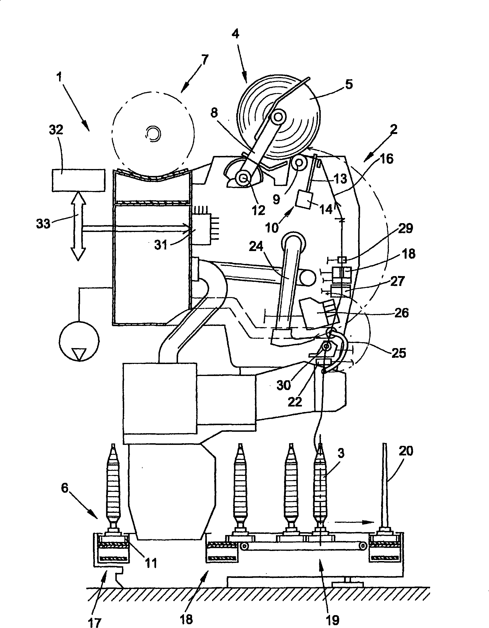
[0023] figure 1 A side view of station 2 of a textile machine for producing cross-wound bobbins is schematically shown. In this example, the textile machine is a so-called automatic cross-winding textile machine 1 . Since this type of textile machine is known, it will not be described in detail. On the station 2 of the automatic cross-winding textile machine 1, the worsted bobbins 3 produced on the spinning frame are rewound so as to form large volume of cross-wound bobbins 5 .

[0024] As soon as they are completed, the cross-wound bobbins 5 are transferred in the longitudinal direction of the machine to the cross-wound bobbin conveyor 7 by means of an automatically operating service unit (not shown), preferably a so-called cross-wound bobbin changer, and conveyed to the bobbin loading station or similar at the end of the machine. Automatic cross-winding textile machines 1 of this type usually also have a supply device in the form of a bobbin and bobbin delivery system 6 ....


PUM


Abstract

The present invention relates to a method for threading a thread (16) into a guide slot (21) of an individually driven, finger-shaped thread guide (13) of a textile machine, which thread guide (13) guides the thread (16) parallel to the spool axis via an oscillating stroke width in order to transfer a thread (16) on a rotating spool (5), wherein the thread guide (13) is transferred into an initial position (A) before the beginning of the threading operation; the thread guide (13) is then transferred into a threading position (E) and drives the thread (16) which is to be threaded in; a relative movement is generated here between the thread guide (13) and the thread (16), in order to thread the thread (16) into the thread guide (16); and the thread (16) is held with tension for the threading operation.

Description

technical field [0001] The invention relates to a method of operating a textile machine as stated in the preamble of claim 1 . Background technique [0002] In textile machines producing bobbins (e.g. winding machines or open-end textile machines), it is arranged to activate the yarn connection in the event of interruptions in the yarn supply due to yarn breakage or replacement of bobbins or bobbins and similar causes operation to resume normal operation. In this case, after the yarn breaks, the yarn is usually located outside the yarn guide (which traverses the yarn during winding), so when the yarn connection is completed, the yarn must return to the guide. in the yarn container. [0003] DE 39 30 136 A1 discloses a method for passing a yarn through a yarn guide at the winder of a textile machine, the yarn being transferred by means of a yarn transfer device to a separately driven back and forth yarn guide. For this purpose, the movement of the yarn transfer device and ...

Claims


Application Information

Patent Timeline
IPC IPC(8): B65H54/28B65H67/08
CPCB65H54/2827B65H57/003B65H67/085B65H2701/31
Inventor 赫尔穆特・科伦赫伯特・吕斯肯斯哈拉尔德・米勒斯亚历山大・马克思诺伯特・科雷斯
Owner SAURER GERMANY GMBH & CO KG
Why Eureka
Try Eureka