Method and mechanism for cleaning beach sand

A beach and sand technology, applied in applications, cleaning equipment, household appliances, etc., can solve the problem of high energy consumption and achieve high productivity and good cleaning quality

Inactive Publication Date: 2008-09-17
拉姆欧洲公司
View PDF5 Cites 8 Cited by
  • Summary
  • Abstract
  • Description
  • Claims
  • Application Information

AI Technical Summary

Problems solved by technology

[0004] All known mechanisms for cleaning beaches - such as the one mentioned here - convey and sift large quantities of clean sand, require screens or ...

Method used


Image

  • Method and mechanism for cleaning beach sand
  • Method and mechanism for cleaning beach sand

Examples


Embodiment Construction

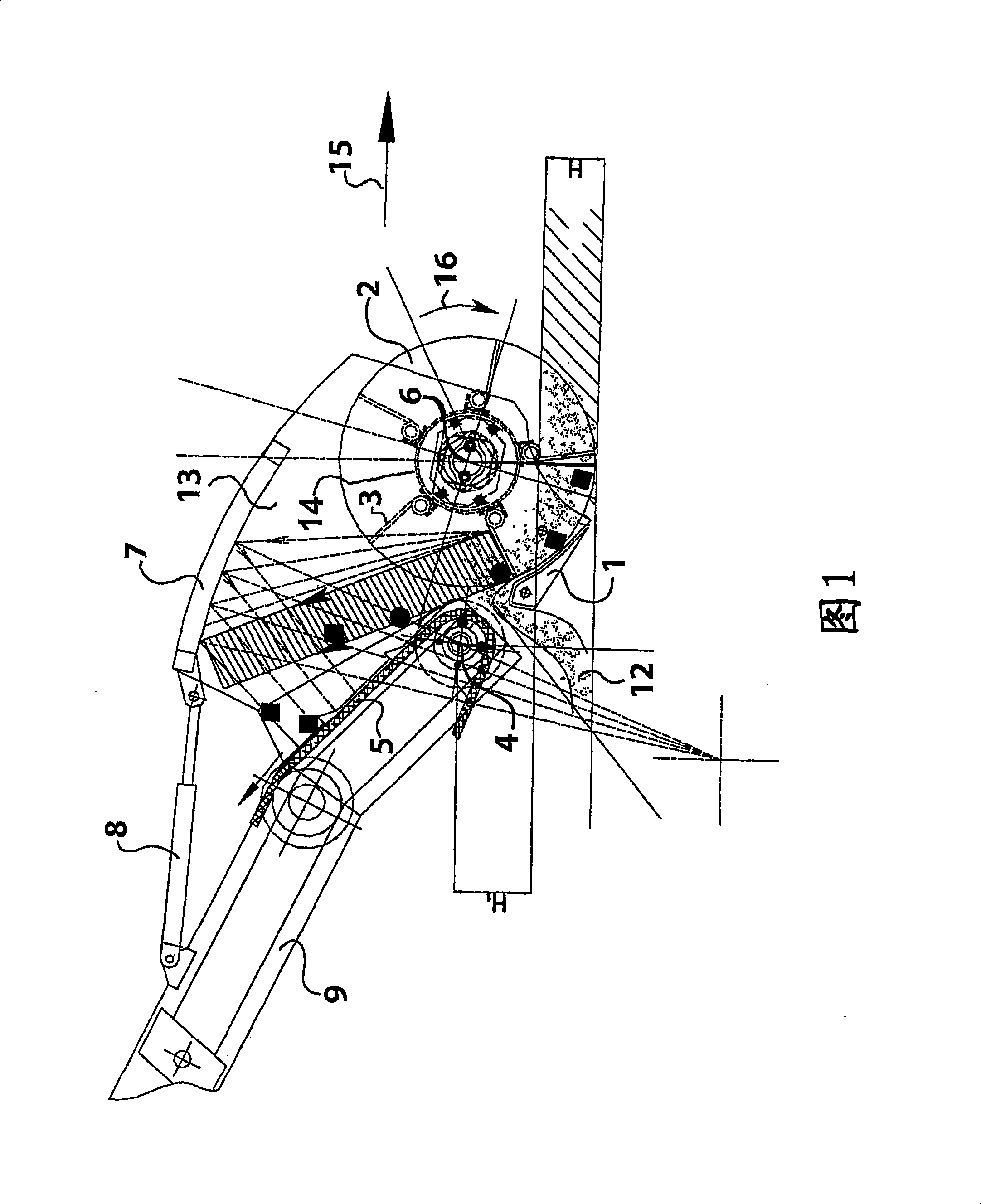
[0013] The important elements of this special mechanism are:

[0014] a) The rotor (2) formed by a metal cylinder (14) equipped with metal spikes (3) whose edges terminate in a cylindrical surface of suitable diameter so as to meet the requirements of the working depth (H) need. The spikes are fixed equidistantly along a line parallel to the axis of the cylinder, or on a helix. Figure 1 shows the rotor (2) of the mechanism for churning sand according to the invention, preferably with 5 sets of spikes. The length of the spike should preferably be about 60% of the radius of the cylindrical surface. During the rotation of each spike, the edge of each spike turns over the cylindrical surface, the axis of which is equal to the rotor width. The number of spikes, the distance between each set of spikes, and the positioning of each set of spikes were set such that there was about 1 mm of clearance between the tracks the spikes left on the ground across the working width. This stru...


PUM

PropertyMeasurementUnit
Radiusaaaaaaaaaa

Abstract

A method having two separate work phases , where, during the first one, the sand destined to be cleaned is stirred up by a rotor (2) , which rotates at a steady rotation speed, whilst the mechanism passes over the surface of sand to be cleaned. During stirring up the waste encountered in the whole working depth are ejected onto a conveyor belt (5) together with a small quantity of stirred sand and then directed to screens where the sand is separated and the remaining waste is ejected into a waste bucket. During the second work phase, the major proportion of the stirred sand, which is now clean, is moved in a flow (12) between the sphenoid blade (1) and the conveyor belt, without any waste, and distributed on the ground. An advantage of this invention is the economy of energy consumption and the improvement of beach sand cleaning machinery performance.

Description

technical field [0001] The invention relates to a motor vehicle or trailer equipped with a special mechanism based on a special method for removing various wastes from beach sand. Background technique [0002] Internationally known beach waste removal mechanisms are equipped with rotating cylinders (rotors) operating in a specific way in which they drive the sand along with the waste onto a rotating conveyor belt so that after sieving , the collected waste will be discharged into the trash can in the usual way. [0003] Devices are also known internationally which scoop up the sand laden with waste by means of wedge-shaped blades and drive the sand towards a conveyor belt in order to remove the waste after sieving. The aforementioned mechanisms and / or combinations of these mechanisms equipped with rotors are mentioned in patents such as US 2002170765, JP 2004324399, US 6094847, JP 4174114 and 0486053 B1. [0004] All known mechanisms for cleaning beaches - such as the one ...

Claims


Application Information

Patent Timeline
IPC IPC(8): E01H12/00
CPCE01H12/00
Inventor 安德烈亚斯・伦佐斯帕拉斯凯维・伦祖
Owner 拉姆欧洲公司
Why Eureka
Try Eureka