Device for the ultrasound testing of hot rolling material

A technology of ultrasonic and material rolling, which is applied in the direction of material analysis, measuring device, and length measuring device using sound wave/ultrasonic wave/infrasonic wave, which can solve the problems of inspection size limitation and achieve the effect of large ultrasonic inspection area

Inactive Publication Date: 2008-09-17
GEORGSMARIENHUTTE
View PDF1 Cites 1 Cited by
  • Summary
  • Abstract
  • Description
  • Claims
  • Application Information

AI Technical Summary

Problems solved by technology

[0007] Another important disadvantage of the previously disclosed device is the limitation of the test size

Method used


Image

  • Device for the ultrasound testing of hot rolling material
  • Device for the ultrasound testing of hot rolling material
  • Device for the ultrasound testing of hot rolling material

Examples


Embodiment Construction

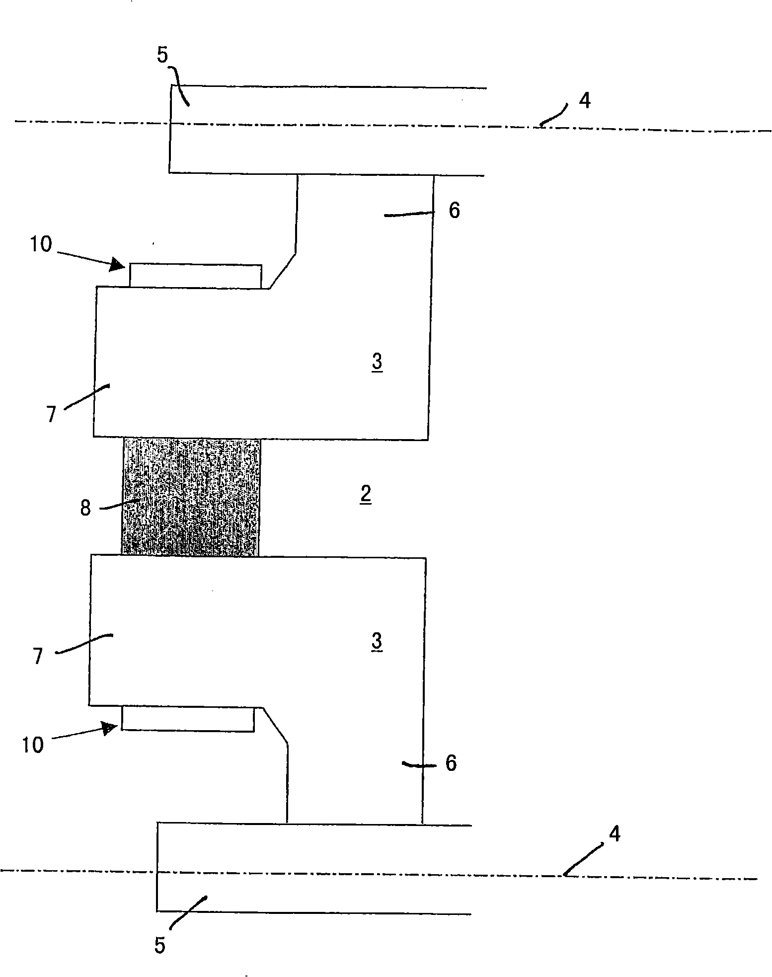
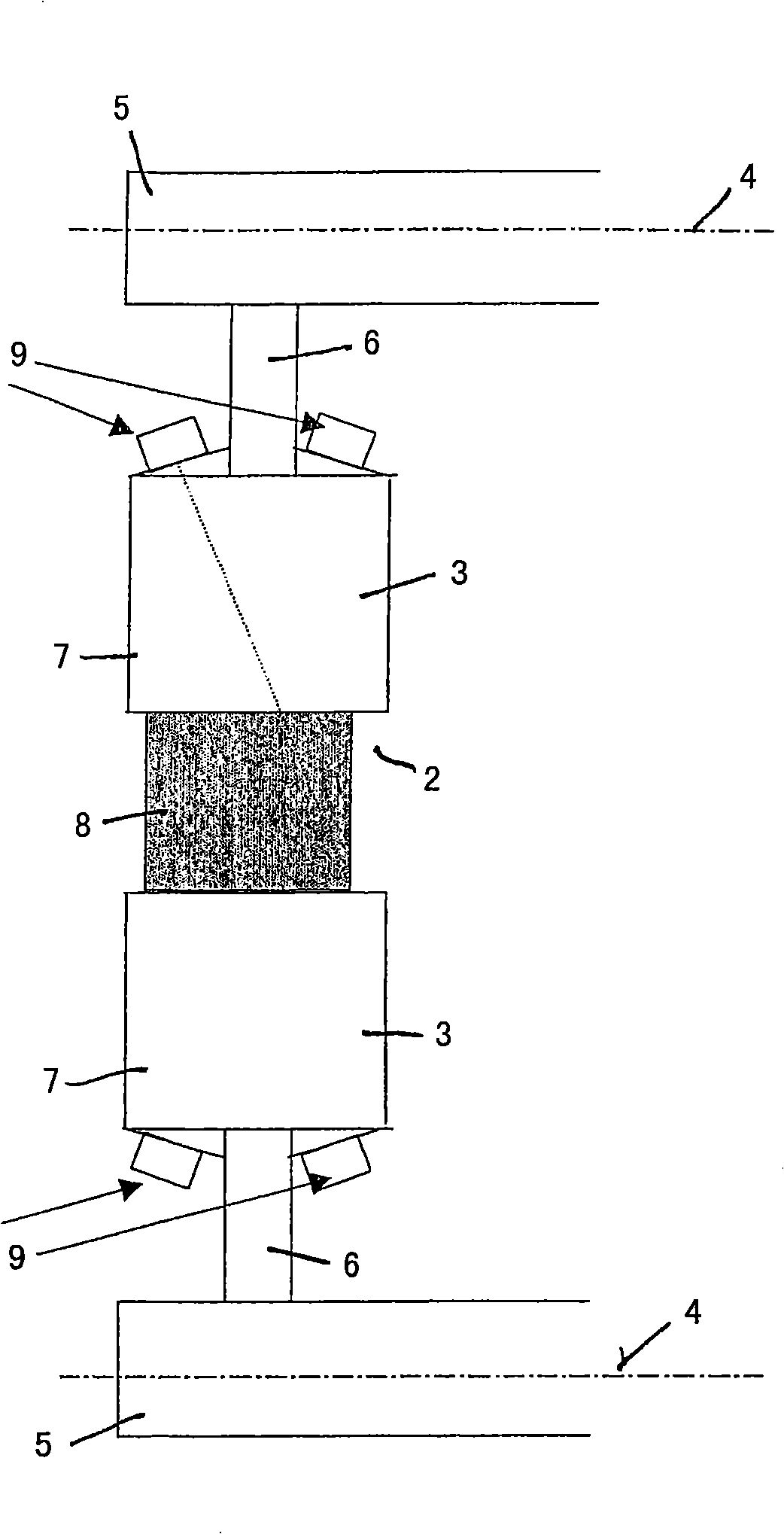
[0026] exist figure 1 and figure 2 A rolling stand is shown in a partial view and is collectively assigned the reference numeral 1 .

[0027] The rolling stand basically comprises two cantilevered rolls 3 with a roll gap 2 between them, the shaft 5 forming the axis of rotation 4 of these cantilevered rolls. The rolls 3 each have a roll disc 6 and an annular extension 7 projecting laterally outward from the roll disc. The rolling stock 8 to be tested is located between the protruding regions 7 of the rolls 3 .

[0028] The actual testing device 9 is arranged on the side of the extension 7 facing the shaft 5 , aligned with the roll gap 2 or the rolling stock 8 .

[0029] here, in figure 1 This is the case with conventional ultrasonic test heads, which are arranged in an array and wired in such a way that they can be controlled individually, with respect to the sound propagation direction and intensity.

[0030] exist figure 2 in all figure 1 Components in are provided w...


PUM


Abstract

The invention relates to a device for the ultrasonic testing of hot rolled material during the welding operation in one of a number of rolling stands of a rolling train that are arranged one behind the other, comprising at least two rollers, leaving a rolling gap between them, the rollers being assigned ultrasonic testing heads which are arranged in such a way that parts of the roller body itself serve as a path along which the ultrasound waves pass to the rolled material to be tested that is in the rolling gap, which device is characterized in that the rollers provided with the ultrasonic testing heads are adjustable, have a straight transverse profile and a diameter which is a multiple of the rolling gap width, so that there is a great rolling angle (a), and these rollers are arranged in one of the first rolling stands of the rolling train.

Description

technical field [0001] The invention relates to a device for the ultrasonic inspection of hot-rolled material during the rolling process in one of a plurality of successively arranged rolling stands of a rolling mill train, comprising at least two with a roll retained between them Gap rolls, wherein ultrasonic testing heads are assigned to these rolls, these ultrasonic testing heads are arranged in such a way that parts of the roll bodies themselves serve as passages for the ultrasonic waves to the rolling stock to be tested in the roll gap. Background technique [0002] Such a device is known, for example, from DE 199 15 203 C2. The device described there is an arrangement in a rolling stand which is positioned in front of the finishing stand during the rolling process. That is, here the steel has been almost completely rolled into its desired shape. As a result, the detection of defects within the rolled material, ie, inclusions, for example, becomes more difficult due t...

Claims


Application Information

Patent Timeline
Patent Type & Authority Applications(China)
IPC IPC(8): G01N29/22
CPCG01N29/228B21B38/00G01N29/043G01N29/11G01N29/262G01N29/27G01N2291/106G01N2291/2632G01N29/00G01N29/22
Inventor A·施蒂贝尔P·范许伦
Owner GEORGSMARIENHUTTE
Why Eureka
Try Eureka