
Motor vehicle lock, in particular motor vehicle door lock

A technology for motor vehicle door locks and motor vehicles, which is applied in the direction of electric vehicle locks, electric locks, vehicle locks, etc., which can solve the problems of unfavorable simple and fast installation, rough stop molding parts, etc., and achieve easy manufacturing and assembly, simple structure Effect

Pending Publication Date: 2021-05-07
KIEKERT & KOMMANDITGES
View PDF11 Cites 0 Cited by
  • Summary
  • Abstract
  • Description
  • Claims
  • Application Information

AI Technical Summary

Problems solved by technology

However, the rough features of the known stop profiles are not conducive to easy and quick installation

Method used


Image

  • Motor vehicle lock, in particular motor vehicle door lock
  • Motor vehicle lock, in particular motor vehicle door lock

Examples


Embodiment Construction

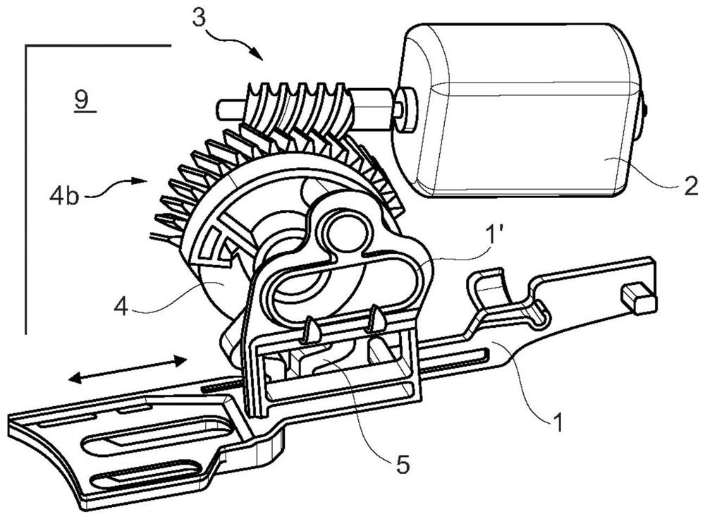
[0023] A motor vehicle lock is shown in the drawing. The motor vehicle lock is here a motor vehicle door lock, but is not limited to a motor vehicle door lock. It has a locking mechanism, not explicitly shown, which essentially consists of a locking fork and a pawl interacting with it. Another basic structure also comprises a locking element 1, which in the case of the exemplary embodiment is a locking bar 1, which essentially follows the figure 1 The double arrow shown executes figure 1 Linear positioning motion shown.

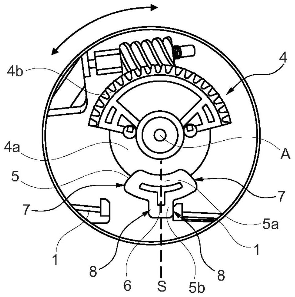
[0024] To this end, the locking element or locking lever 1 is connected to an electric drive 2 , 3 , 4 . The electric drive 2 , 3 , 4 consists of an electric motor 2 , an output worm 3 driven by the electric motor 2 and a worm wheel 4 meshing with the output worm 3 .

[0025] from figure 1 with figure 2As can be seen from the comparison of , the worm wheel 4 is specifically equipped with a base portion 4a and a worm wheel ring portion 4b. The base 4a ...


PUM


Abstract

The invention relates to a motor vehicle lock, in particular a motor vehicle door lock, comprising a locking mechanism, at least one lock element (1) and an electric drive device (2, 3, 4). Furthermore, a stop profile (5) is provided which is common to the lock element (1) and the drive device (2, 3, 4). According to the invention, the stop profile (5) is equipped with a single central cavity (6) which is surrounded by a peripheral ridge, said ridge defining at least one stop (7) for the drive device (2, 3, 4) and at least one stop (8) for the lock element (1).

Description

technical field [0001] The invention relates to a motor vehicle lock, in particular a motor vehicle door lock, having a locking mechanism, at least one locking element and an electric drive, and having a common stop profile / stop contour for the lock element and the drive. Background technique [0002] Motor vehicle locks include in particular motor vehicle door locks, but also motor vehicle hatch locks, motor vehicle hood locks, motor vehicle locks for fuel tank caps, tailgates and the like. In order to lock and unlock such a vehicle lock eg centrally, the above-mentioned electric drive acts on a lock element, which in the example described is a locking lever or generally a locking element. Thus, by means of an electric drive, the locking element can be shifted into at least the "unlocked" and "locked" positions. In principle, depending on the design of the locking element or locking element, functional positions such as "theft-proof", "not-theft-proof", "childproof" and "n...

Claims


Application Information

Patent Timeline
IPC IPC(8): E05B83/36E05B81/06E05B81/32E05B85/00
CPCE05B83/36E05B81/06E05B81/32E05B85/00E05B81/25E05B81/38E05B81/36E05B81/16E05B85/26
Inventor 孙淳镐
Owner KIEKERT & KOMMANDITGES
Learn More