Variable color light emitting device and method for controlling the same

A light-emitting device, color-changing technology, applied in the direction of electric solid-state devices, semiconductor devices, electrical components, etc., can solve the problem of occupying a large amount of space, to increase the radiation area, reduce expensive or low-efficiency, and do not occupy space Effect

Inactive Publication Date: 2008-09-17
KONINKLIJKE PHILIPS ELECTRONICS NV
View PDF2 Cites 37 Cited by
  • Summary
  • Abstract
  • Description
  • Claims
  • Application Information

AI Technical Summary

Problems solved by technology

[0006] Another disadvantage of using several individual light sources is that they take up unnecessarily large amounts of space

Method used


Image

  • Variable color light emitting device and method for controlling the same
  • Variable color light emitting device and method for controlling the same
  • Variable color light emitting device and method for controlling the same

Examples


Embodiment Construction

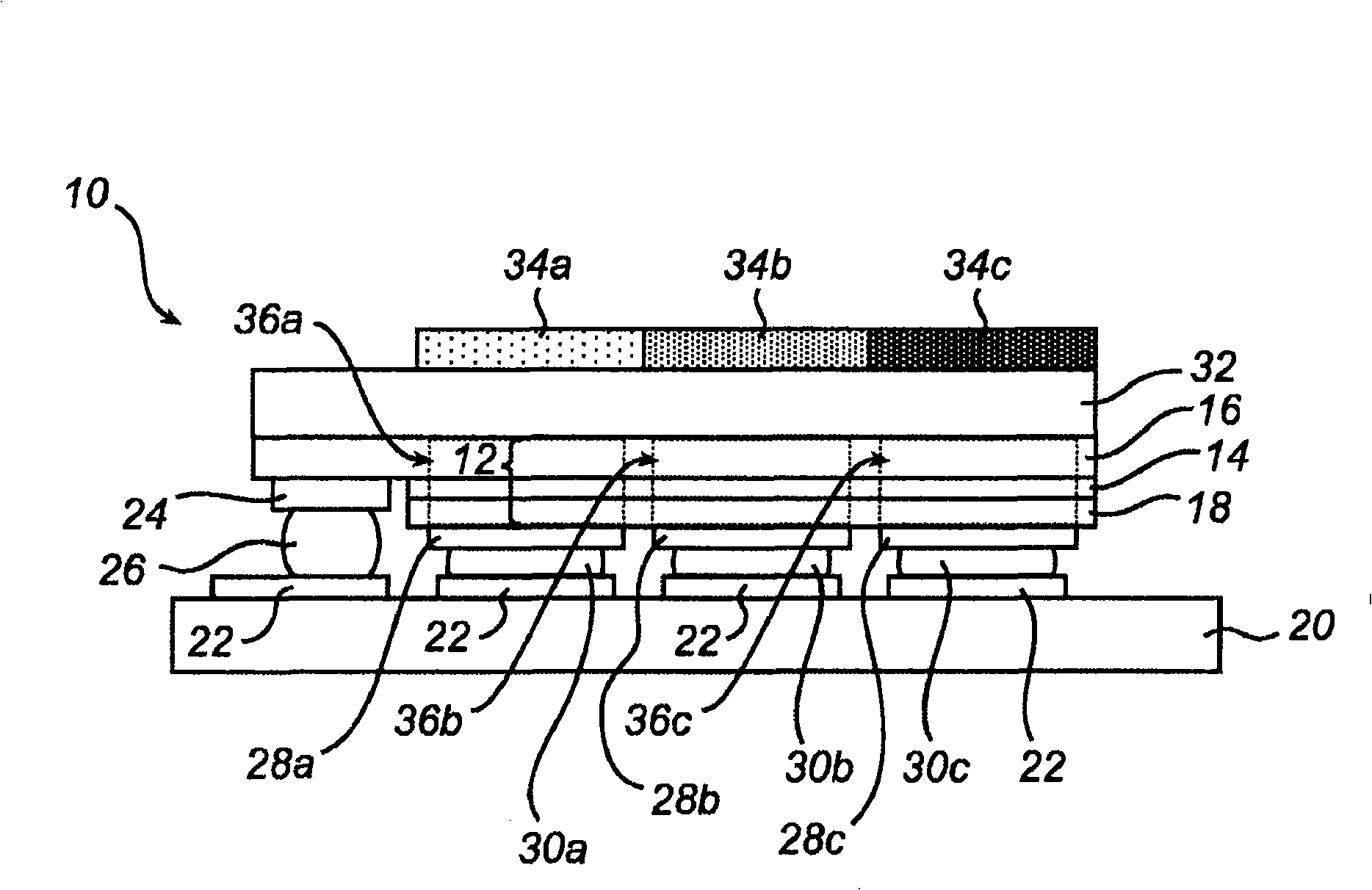
[0041] figure 1 is a cross-sectional side view of a color-variable light emitting device 10 according to an embodiment of the present invention. The light emitting device 10 includes a light emitting diode 12 which in turn includes an active layer 14 disposed between an N-type layer 16 and a P-type layer 18 . These layers can be, for example, suitably doped GaN layers. The diodes 12 are mounted on a submount 20 provided with electrical contacts 22 connected to circuitry (not shown) for driving the diodes. The N-type layer 16 is provided with a contact 24 soldered (by means of a solder bump 26) to one of the electrical contacts 22, thereby connecting the N-type layer 16 to the circuit driving the diode. P-type layer 18 is similarly connected to the circuit by means of contacts 28 a - 28 c , solder bumps 30 a - 30 c and electrical contact 22 . On top of the N-type layer 16 is provided a transparent substrate 32 on top of which are provided wavelength converters 34a-34c.

[0...


PUM


Abstract

The present invention relates to a variable color light emitting device (10) comprising a light emitting diode (12) for emitting light, which diode in turn comprises a plurality of electrically conducting layers (14, 16, 18) , at least one of which being such that lateral current spreading in the diode is limited to form at least two independently electrically addressable segments (36) , for allowing illumination of an optional number of the segments. At least one of the number of segments is provided with a wavelength converter (34) adapted to convert at least part of the light emitted from its associated segment to generate light of a certain primary color. The invention also relates to systems incorporating at least one such light emitting device and a method for controlling such a light emitting device.

Description

technical field [0001] The present invention relates to a variable color light emitting device, a system comprising at least one such light emitting device, and a method of controlling such a light emitting device. Background technique [0002] It is known that combining projected light of one color with projected light of another color produces a third color. It is also known that the three most commonly used primary colors (ie red, green and blue) can be combined in various proportions to produce almost any color in the visible spectrum. [0003] These understandings are widely used in various color-changing lighting systems, where different colors can be produced by mixing primary colors in a predetermined manner. Such systems are used, for example, for lighting purposes. One such system is disclosed in patent document US6016038. In US6016038 and other known variable color lighting systems and multicolor light emitting devices, a single light source, namely a light emi...

Claims


Application Information

Patent Timeline
Patent Type & Authority Applications(China)
IPC IPC(8): H01L27/15H01L33/50
CPCH01L27/153H01L33/504H01L33/50H01L33/08
Inventor C・J・加林克G・H・M・范塔特威克C・G・A・霍伦
Owner KONINKLIJKE PHILIPS ELECTRONICS NV
Why Eureka
Try Eureka