
Wireless communication antenna module and mobile terminal composed of it

A wireless communication and antenna module technology, which is applied to antennas, loop antennas, antenna components, etc., can solve the problems of weak receiving performance, weak signal strength, and shortened readable pattern recognition distance, and achieve the improvement of radiation area and improvement Effect of Antenna Characteristics

Active Publication Date: 2017-11-14
AMOTECH
View PDF8 Cites 0 Cited by
  • Summary
  • Abstract
  • Description
  • Claims
  • Application Information

AI Technical Summary

Problems solved by technology

Therefore, due to the weak signal strength of the received signal in the existing wireless communication antenna module, the receiving performance becomes weaker in the readable mode, resulting in the problem that the recognition distance of the readable mode becomes shorter.

Method used


Image

  • Wireless communication antenna module and mobile terminal composed of it
  • Wireless communication antenna module and mobile terminal composed of it
  • Wireless communication antenna module and mobile terminal composed of it

Examples


Embodiment Construction

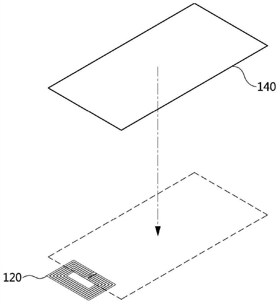
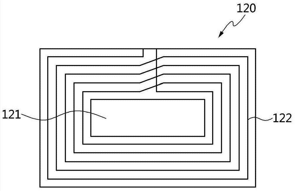
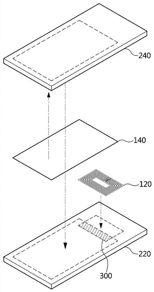
[0028] Hereinafter, preferred embodiments of the present invention will be described in detail with reference to the accompanying drawings in order to enable those skilled in the art to which the present invention pertains and have ordinary knowledge to easily understand and implement the technical idea of ​​the present invention. First of all, it should be noted that the same reference numerals are used as much as possible even if the reference numerals of the constituent elements in each drawing appear in different drawings. Once again, if it is considered that the specific description of the relevant known functions and structures is unnecessary or confusing to explain the gist of the present invention, then it will be omitted

[0029] The wireless communication antenna module according to the first embodiment of the present invention will be described in detail below with reference to the accompanying drawings. Figure 1 to Figure 5 It is a schematic diagram illustrating th...


PUM


Abstract

The present invention provides a wireless communication antenna module in which a radiation plate and a part of an antenna plate are overlapped to maximize antenna performance, and a mobile terminal composed of the same. The wireless communication antenna module includes an antenna plate, formed with a radiation pattern, installed on the mobile terminal host or battery pack; and a radiation plate, installed on the rear shell of the mobile terminal, based on the combination of the mobile terminal host and the rear shell , the antenna board and the radiation board are overlapped to form a stack and form an overlapping area.

Description

technical field [0001] The present invention relates to a wireless communication antenna module, more specifically, to a wireless communication antenna module built in a mobile terminal for communicating with a wireless communication antenna module built in another mobile terminal and a mobile terminal composed of the wireless communication antenna module. [0002] The present invention claims the priority of patent application Nos. 10-2013-0015842 and 10-2014-0017221 filed with the Korean Intellectual Property Office on February 14, 2013 and February 14, 2014, the contents of which all belong to this invention. Background technique [0003] With the development of technology, mobile terminals such as mobile phones, handheld computers, personal multimedia players, navigators, and notebook computers provide not only basic functions such as calls, video or audio playback, and navigation, but also digital media broadcasting and wireless Internet. , Short-distance communication...

Claims


Application Information

Patent Timeline
Patent Type & Authority Patents(China)
IPC IPC(8): H01Q7/00
CPCH01Q7/00H01Q1/243
Inventor 丁乙荣白亨一金范镇李雉浩李到炯
Owner AMOTECH
Learn More