Operation mechanism of self-propelled multifunctional border stone slip form machine

A working mechanism and curb stone technology, applied in the direction of roads, roads, road repair, etc., can solve the problems of increased project cost, high slump requirements, and easy deformation of structures, so as to improve the tensile strength and enhance the compaction effect. , The effect of relative rotation and flexibility

Active Publication Date: 2008-09-24
JIANGSU SIMING ENG MACHINERY
View PDF0 Cites 18 Cited by
  • Summary
  • Abstract
  • Description
  • Claims
  • Application Information

AI Technical Summary

Problems solved by technology

[0002] The connection between the forming mold and the mold hopper of the existing self-propelled sliding form machine adopts a rigid method. In the case of hard concrete, steps and indentations often appear on the surface of the curb, and satisfactory flatness cannot be obtained; at the same time, because the dense dry hard concrete in the rigid mold is not easy to deform, the rigid mold must overcome when the traction main engine advances. The shear resistance of dense concrete, if the width of the paved curb is large, the shear resistance will be greater, and the slipform machine will slip when it advances on the roadbed, causing the slipform machine to break when it is running. Continued, unable to control the direction, the line of the curb is not beautiful, and it cannot be paved normally
Moreover, the existing slipform machine uses plug-in vibrating rods for dense molding, and the required concrete slump must be stable within a reasonable range; if the concrete slump is too high, the paved structure is prone to deformation ; If the concrete slump is too low, the workability of the concrete is poor, and it is difficult for the vibrating rod to compact it evenly, and the structure will have defects such as incompleteness and internal potholes.
This type of slipform machine has high requirements on the slump of concrete at the construction site. In order to meet this requirement, it is necessary to use a forced mixing station for mixing, and a concrete mixer truck for transportation, which increases the project cost.

Method used


Image

  • Operation mechanism of self-propelled multifunctional border stone slip form machine
  • Operation mechanism of self-propelled multifunctional border stone slip form machine
  • Operation mechanism of self-propelled multifunctional border stone slip form machine

Examples


Embodiment Construction

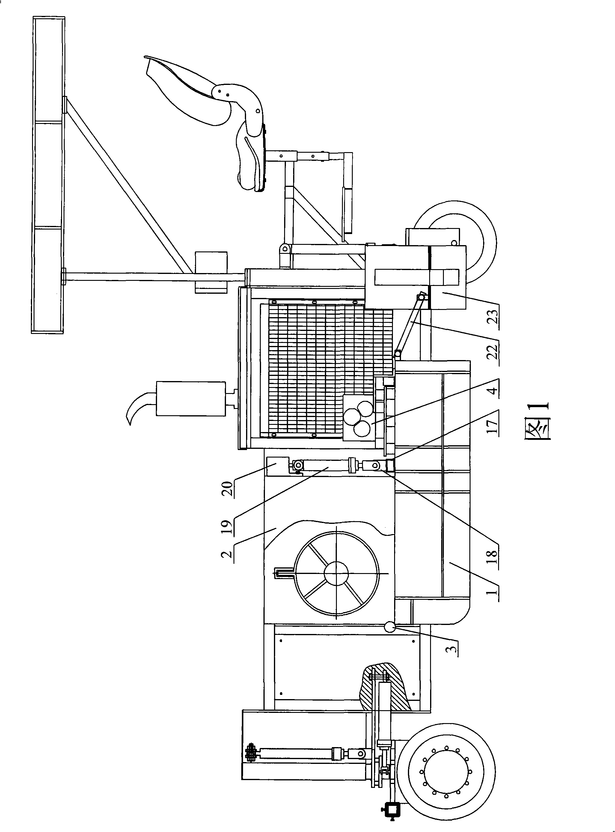
[0032] As shown in FIG. 1 , the forming mold 1 is arranged below the mold hopper 2 and hinged to the mold hopper 2 through a pivot device 3 . The pivot device 3 connects the front plate 1 - 3 of the forming mold 1 and the front side of the mold hopper 2 .

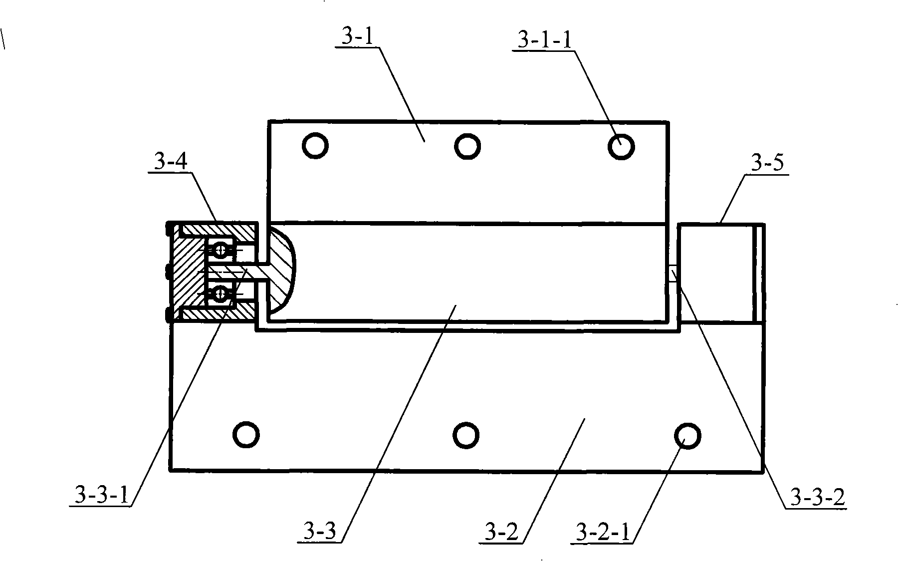
[0033] Such as figure 2As shown, the pivot device 3 includes an upper connecting plate 3-1, a lower connecting plate 3-2, a cylindrical shaft 3-3, a first bearing mechanism 3-4 and a second bearing mechanism 3-5. The lower side of the upper connecting plate 3-1 is welded to the outer surface of the cylindrical shaft 3-3 along the length direction of the cylindrical shaft 3-3. The first bearing mechanism 3-4 and the second bearing mechanism 3-5 are welded on the upper side of the lower connecting plate 3-2. A first connecting shaft 3-3-1 is arranged at one end of the cylindrical shaft 3-3, and a second connecting shaft 3-3-2 is arranged at the other end. The above-mentioned cylindrical shaft 3-3 is arranged between the fi...


PUM


Abstract

The invention discloses a forming die working mechanism of a self-propelled type multifunctional curb sliding mode machine in the technical field of concrete continuous paving device. When the working mechanism paves dry hard concrete, a construction has the advantages of stable shaping, high compactness and good planeness; the working mechanism includes a shaping die and a die hopper; the shaping die is arranged below the die hopper; the shaping die includes a front plate, a first side plate and a second side plate; the first side plate and the second side plate are respectively connected at the two sides of the front plate; a template is arranged between the first side plate and the second side plate; the shaping die is hinged with the die hopper through a pivot device; the pivot device is connected with the front plate of the shaping die and the front side surface of the die hopper; besides, the working mechanism also includes an externally arranged oscillator; the oscillator is connected with the template through a connecting frame.

Description

technical field [0001] The invention belongs to the technical field of continuous concrete paving equipment, and in particular relates to a forming mold working mechanism of a self-propelled multifunctional curb sliding form machine. Background technique [0002] The connection between the forming mold and the mold hopper of the existing self-propelled sliding form machine adopts a rigid method. In the case of hard concrete, steps and indentations often appear on the surface of the curb, and satisfactory flatness cannot be obtained; at the same time, because the dense dry hard concrete in the rigid mold is not easy to deform, the rigid mold must overcome when the traction main engine advances. The shear resistance of dense concrete, if the width of the paved curb is large, the shear resistance will be greater, and the slipform machine will slip when it advances on the roadbed, causing the slipform machine to break when it is running. Continuing, the direction cannot be cont...

Claims


Application Information

Patent Timeline
Patent Type & Authority Applications(China)
IPC IPC(8): E01C19/48
Inventor 赵国普何慧国郝名洪朱春明盛龙英
Owner JIANGSU SIMING ENG MACHINERY
Why Eureka
Try Eureka