Self-sealing joint

A self-sealing and joint technology, applied in the direction of mechanical equipment, couplings, etc., can solve the problems of uneven force distribution of the sealing spool, wear of the sealing spool, sealing gap of the self-sealing joint, etc., to prevent wear and natural inclination , to ensure the effect of verticality

Inactive Publication Date: 2008-09-24
宁波中迪机械有限公司
View PDF0 Cites 17 Cited by
  • Summary
  • Abstract
  • Description
  • Claims
  • Application Information

AI Technical Summary

Problems solved by technology

[0003] Although the above two types of self-sealing joints can enable the staff to easily install, disassemble and maintain the instrument or valve body when the system has a pressure source, they all have the following defects: 1. Type self-sealing joints do not have interference extrusion protection for the sealing spool, so in the frequent contact between the sealing spool and the sealing ring surface or the sealing hole end, it is easy to cause the sealing spool to wear, so that the sealing gap appears in the self-sealing joint; 2. Due to the error of verticality after the return spring is installed, the force of the return spring acting on the sealing spool is not uniform, which makes the wear of the sealing surface uneven, which easily causes the natural inclination of the sealing spool to form seal gap

Method used


Image

  • Self-sealing joint
  • Self-sealing joint

Examples


Embodiment Construction

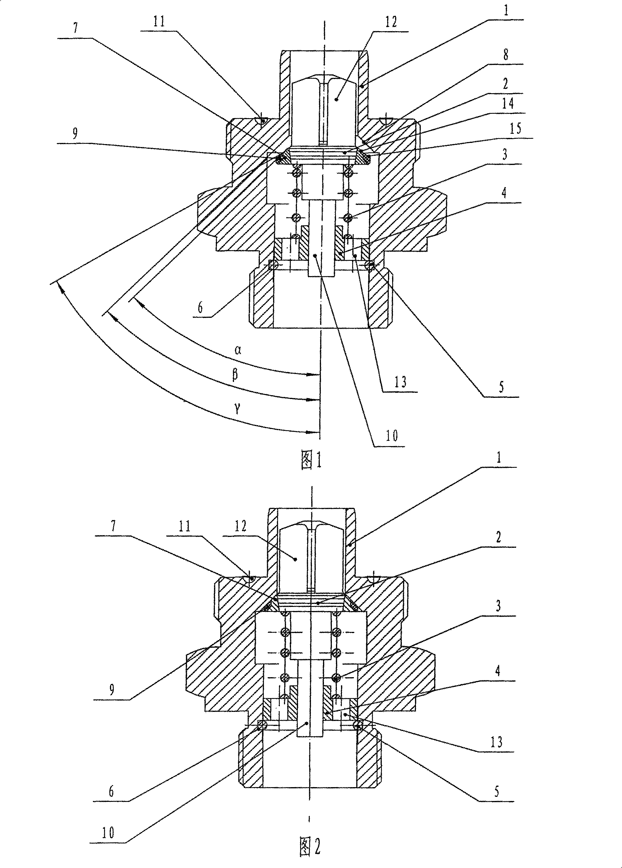
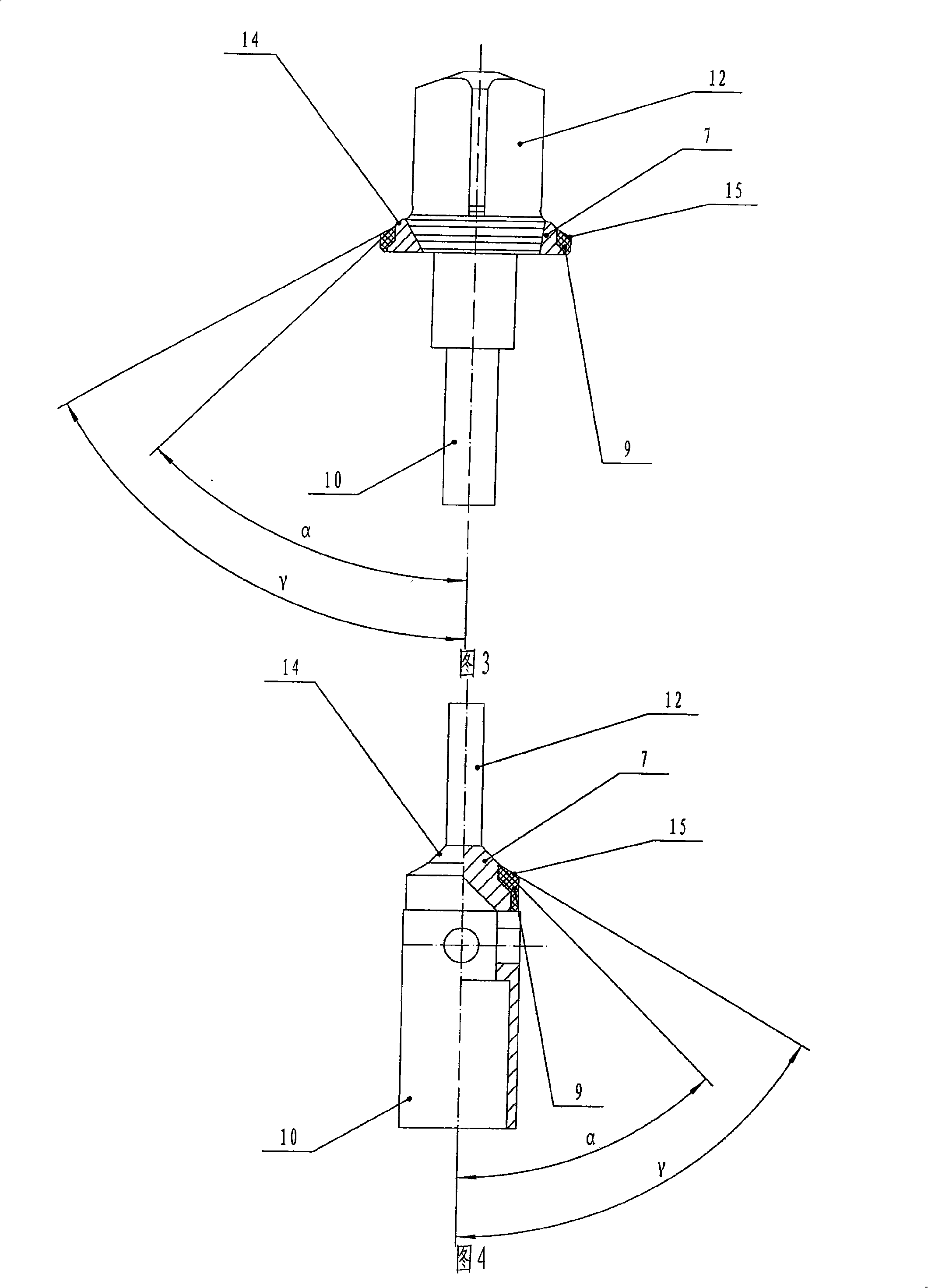
[0016] The present invention will be further described below in conjunction with accompanying drawing and specific embodiment:

[0017] As shown in Figure 1, Figure 2 and Figure 3, in this specific embodiment, the self-sealing joint of the present invention includes a joint body 1, a sealing valve core 2 located in the joint body 1, a return spring 3, and a valve for liquid circulation. The spring seat 4 of the through hole 13 and the limit retaining ring 5; the limit retaining ring 5 is placed on the groove 6 of the inner wall of the joint body 1; The concave seal groove 11 used in cooperation with the protrusion on the not shown in the middle); the spring seat 4 is connected to the top of the stop ring 5; the guide rod 10 of the sealing valve core 2 is slidably matched with the center hole of the spring seat 4 The top of the back-moving spring 3 rests on the middle part of the sealing valve core 2, and the bottom of the back-moving spring 3 rests on the spring seat 4; the jo...


PUM


Abstract

The invention discloses a self-sealing joint. The invention comprises a joint body (1) which is provided with a sealing surface (8) of the joint body; a sealing valve core (2), a limiting shield ring (5), a spring seat (4) and a reset spring (3) of a metal limiting scapular (7) which are applied in combination with the sealing surface (8) of the joint body are mounted at the middle part along the axial direction; a ring shaped inclined plane (14) is mounted at the top part of the metal limiting scapular (7); both the angle (Alpha) between the ring shaped inclined plane (14) and the axis of the sealing valve core (2) and the angle (Beta) between the sealing surface (8) of the joint body and the axis of the joint body (1) can be 44 degrees to 46 degrees; the top part of a sealing ring (9) is an inclined plane (15); the sealing ring (9) is embedded at the lower part of a metal limiting scapular (2); the angle (Gamma) between the inclined plane (15) and the axis of the sealing valve core (2) can be 59 degrees to 61 degrees when the sealing ring (9) is in a natural state. The invention has no sealing space and the sealing valve core is protected from abrasion.

Description

Technical field: [0001] The invention relates to an online quick connection device used in a fluid pressure control system, in particular to a self-sealing joint. Background technique: [0002] The fluid pressure control system is basically composed of pipes, instruments, joints, valve bodies and other components, and the maintenance of the system and the replacement of instruments usually need to close the pressure source before proceeding, which brings great inconvenience to the loading and unloading and maintenance of instruments or valve bodies. Great inconvenience. In order to enable the staff to conveniently install, disassemble and maintain the instrument or valve body when the system has a pressure source, at present, there are two different types of self-sealing joints in the prior art, one of which is a cover The cover type is the soft contact between the sealing spool (seal piston) in the joint body and the sealing surface of the joint body; the other type is the...

Claims


Application Information

Patent Timeline
Patent Type & Authority Applications(China)
IPC IPC(8): F16L37/40
Inventor 王重杰
Owner 宁波中迪机械有限公司
Why Eureka
Try Eureka