Calibration compensation method for rotating transformer angle observation error based on velocity rotating platform

A technology of resolver and rate turntable, which is applied in the direction of instruments, uses electric/magnetic devices to transmit sensing components, etc., can solve the problems of discontinuity, inability to describe the short-cycle variation law of resolvers, and unsatisfactory calibration results, and achieves improved performance. The effect of angle measurement accuracy

Inactive Publication Date: 2008-09-24
BEIHANG UNIV
View PDF0 Cites 36 Cited by
  • Summary
  • Abstract
  • Description
  • Claims
  • Application Information

AI Technical Summary

Problems solved by technology

The original calibration method adopts the static position calibration test, which can obtain the absolute error of the resolver, but the test data can only be a limi

Method used


Image

  • Calibration compensation method for rotating transformer angle observation error based on velocity rotating platform
  • Calibration compensation method for rotating transformer angle observation error based on velocity rotating platform
  • Calibration compensation method for rotating transformer angle observation error based on velocity rotating platform

Examples


Embodiment Construction

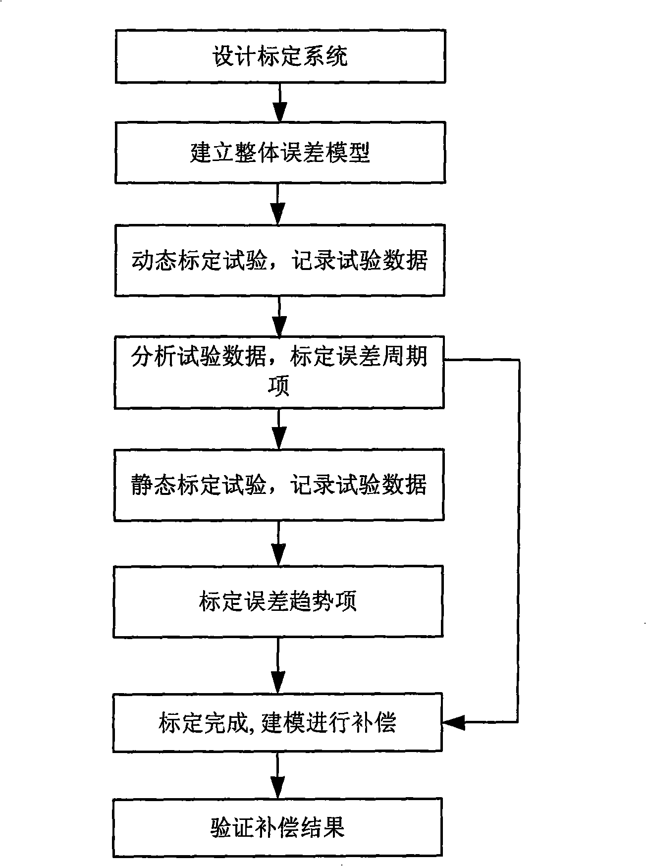
[0016] Such as figure 1 As shown, the present invention firstly designs the digital calibration system of the resolver, and then establishes the overall error model of the resolver. Through the dynamic calibration test of the digital calibration system, the dynamic continuous output of the resolver can be obtained, and the periodic error term coefficient of the resolver can be calibrated , and then through the static calibration test, the angle-related first-order and zero-order errors of the resolver are calibrated. The specific steps are as follows:

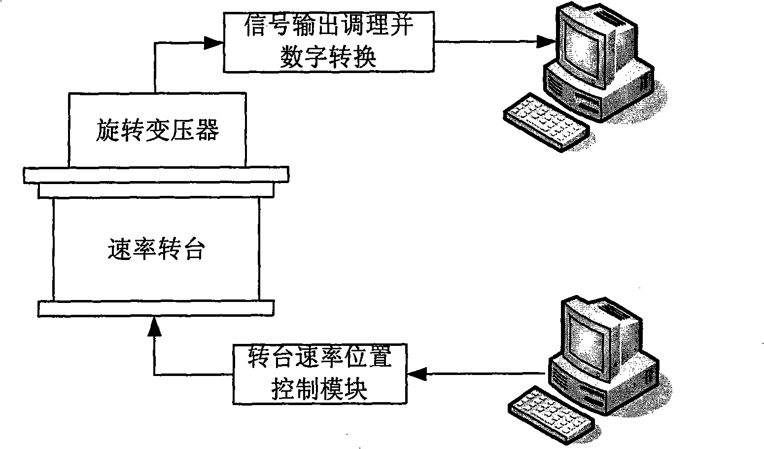
[0017] 1. Design a set of digital calibration system for resolver, such as figure 2 As shown, the digital calibration system is composed of a speed turntable, a turntable speed position control module, a resolver signal output conditioning and a digital conversion module. The speed and position control module adopts a closed-loop method to precisely control the rotation of the turntable according to the given parameters. The ...


PUM


Abstract

A calibration compensation method of angle-measurement error of a rotating transformer based on a rate rotary table; the calibration method obtains the dynamic continuous output of the rotating transformer through a dynamic calibration test of a digital calibration system, so as to calibrate the cycle error term coefficient of the rotating transformer; calibrates the one degree term and zero degree term errors of the rotating transformer through a static calibration test; completes precise error calibration of the rotating transformer through the dynamic and the static tests; and later, builds a model to compensate the calibrated rotary error. The invention integrates the advantages of the dynamic and the static calibration methods, is not restricted by precision of an angle measuring device, is easy and simple; the built error compensation model of the rotating transformer greatly improves the angle-measuring precision of the rotating transformer. The method is also applicable in calibration and compensation of all other shaft angle sensors as well as the angle-measuring precision.

Description

technical field [0001] The invention relates to a method for calibrating and compensating the angle measuring error of a resolver, which is also suitable for calibrating and compensating other various shaft angle sensors, and can greatly improve the angle measuring precision. Background technique [0002] As a shaft angle sensor, the resolver is used in various fields, especially in occasions that require relatively high accuracy of angle measurement. However, due to the limitation of the manufacturing process, there are a series of problems, such as the eccentric installation of the resolver stator and rotor and the relative inclination on the installation, as well as the low stiffness of the shaft itself, resulting in a slight bending of the geometric axis of the shaft system, which will produce rotor and stator disks The eccentricity and relative inclination of the resolver, and the internal winding harmonics of the resolver, the saturation of the magnetic circuit, the cr...

Claims


Application Information

Patent Timeline
IPC IPC(8): G01D18/00G01D5/14
Inventor 张仲毅冯培德张京娟刘俊成李毅
Owner BEIHANG UNIV
Why Eureka
Try Eureka