Sheet material thickness detection tool and method

A technology for thickness detection and sheet material, which is applied in the direction of measuring devices, optical devices, instruments, etc., can solve the problems affecting the accuracy of measuring devices, inaccurate measurement results, uneven water film, etc., and achieve the effect of saving manpower

Active Publication Date: 2018-08-03
YANTAI UNIV
View PDF5 Cites 3 Cited by
  • Summary
  • Abstract
  • Description
  • Claims
  • Application Information

AI Technical Summary

Problems solved by technology

[0008] The plate thickness measuring device works on the industrial site, the ambient temperature changes greatly throughout the year, the laser displacement sensor has a large temperature drift, the distance between the two sensors will change with the ambient temperature, and the parts themselves have thermal deformation , there is an unstable and uneven water film on the surface of the part. These factors will affect the measurement results of the thickness of the plate. The above-mentioned measuring device d

Method used


Image

  • Sheet material thickness detection tool and method
  • Sheet material thickness detection tool and method
  • Sheet material thickness detection tool and method

Examples


Embodiment 1

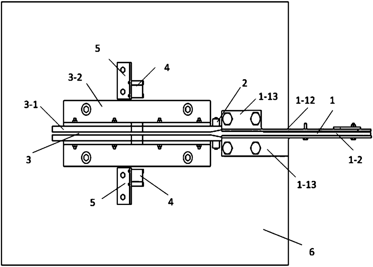
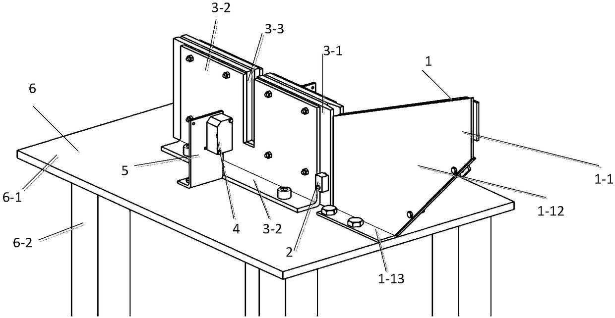
[0074] like Figure 5-Figure 14 As shown, a plate thickness detection tooling includes a workbench 6, a guide groove for conveying the plate, and a laser displacement sensor 4. Both the guide groove and the laser displacement sensor are located on the workbench 6, and the laser displacement The sensor 4 includes two, respectively arranged on both sides of the guide groove, the two groove walls of the guide groove are respectively provided with corresponding gaps 3-3, the gap 3-3 can be a U-shaped groove structure, The gap 3-3 corresponds to the laser displacement sensor 4, a photoelectric switch 2 is provided on the front end side of the guide groove, and an automatic calibration mechanism 11 is provided at the lower end of the guide groove;

[0075] The automatic calibration mechanism 11 includes a calibration plate drive motor 11-1, a calibration plate 11-4 and a connection plate 11-3, and one end of the connection plate 11-3 is connected to the output shaft of the calibrati...

Embodiment 2

[0097] The difference with embodiment 1 is: as Figure 15-16 As shown, it also includes a water absorbing device. The water absorbing device includes two groups, and each group of water absorbing devices includes two symmetrically arranged water absorbing parts 16. The first group of water absorbing devices is arranged in front of the first guide groove 1, and the second group of water absorbing devices The water absorbing device is arranged on both sides of the rotation plane of the calibration plate 11-4;

[0098] The water absorbing part 16 includes a water absorbing roller drive motor 16-1, a rigid coupling 16-3, a water absorbing roller shaft 16-4 and a water absorbing roller 16-5, and the water absorbing roller 16-5 is set on the water absorbing roller shaft 16 -4, the output shaft of the water suction roller drive motor 16-1 is connected to the water suction roller shaft 16-4 through a rigid coupling 16-3, and then drives the water suction roller shaft 16-4 to rotate, a...


PUM


Abstract

The present invention relates to a sheet material thickness detection tool. The tool comprises a workbench, a guide slot configured to transmit sheet materials and laser displacement sensors, the guide slot and the laser displacement sensors are located on the workbench, there are two laser displacement sensors which are respectively arranged at two sides of the guide slot, the two slot walls of the guide slot are respectively provided with corresponding gaps, the gaps are U-shaped slot structures, the gaps correspond to the laser displacement sensors, the front end of the guide slot is provided with an optoelectronic switch, and the lower of the guide slot is provided with an automatic calibration mechanism. The sheet material thickness detection tool can achieve automatic calibration, does not need frequent manual calibration and saves labor. The present invention further relates to a sheet material thickness detection method.

Description

technical field [0001] The invention relates to a detection tool and a detection method for part thickness, in particular to a plate thickness detection tool and a detection method. Background technique [0002] The measurement of the plate in the prior art, such as Figure 1-Figure 4 As shown, need to use two laser displacement sensors S1 and S2, O 1 and O 2 They are the zero points of the laser displacement sensor S1 and the laser displacement sensor S2 respectively, and the left surface of the part is measured by the laser displacement sensor S1 to O 1 The distance is l 1 , measured by the laser displacement sensor S2 from the right side surface of the part to O 2 The distance is l 2 , O 1 with O 2 The distance is L, then the thickness value of the part is: δ=L–l 1 –l 2 . [0003] The existing plate thickness measuring device comprises a workbench, a laser displacement sensor and a guide groove. The workbench includes a workbench and a pillar. Both the sensor an...

Claims


Application Information

Patent Timeline
IPC IPC(8): G01B11/06
CPCG01B11/06
Inventor 王东兴冷惠文
Owner YANTAI UNIV
Why Eureka
Try Eureka