Resin sealing method, mold for resin sealing, and resin sealing apparatus
A resin sealing and resin technology, applied in the field of mold and resin sealing equipment, resin sealing mold and resin sealing equipment, to achieve the effect of simplifying structure, reducing cycle time and improving production efficiency
- Summary
- Abstract
- Description
- Claims
- Application Information
AI Technical Summary
Problems solved by technology
Method used
Image
Examples
no. 1 example
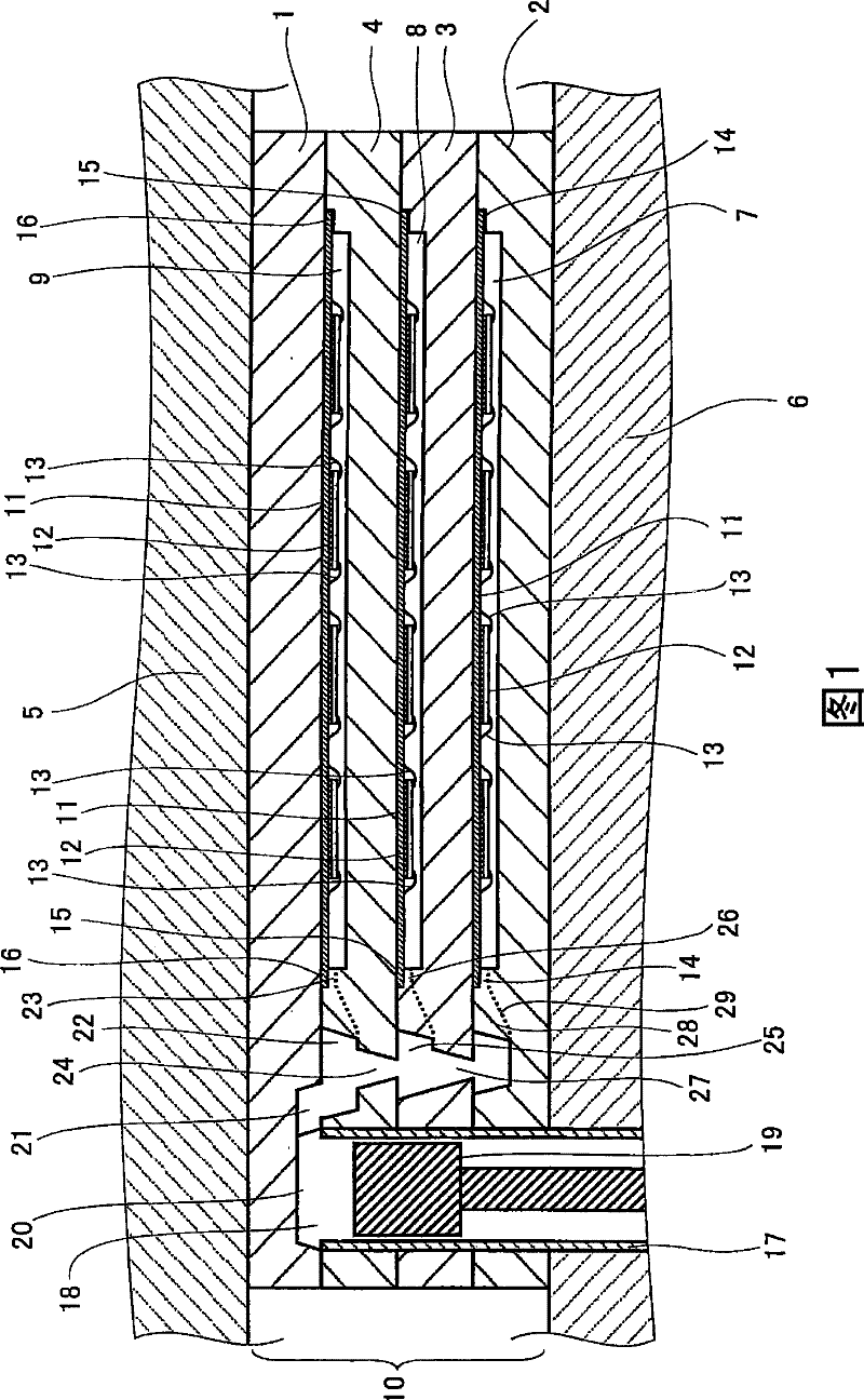
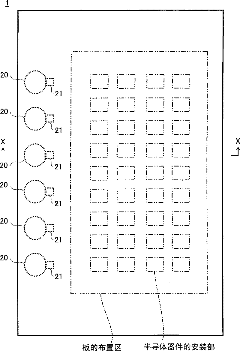
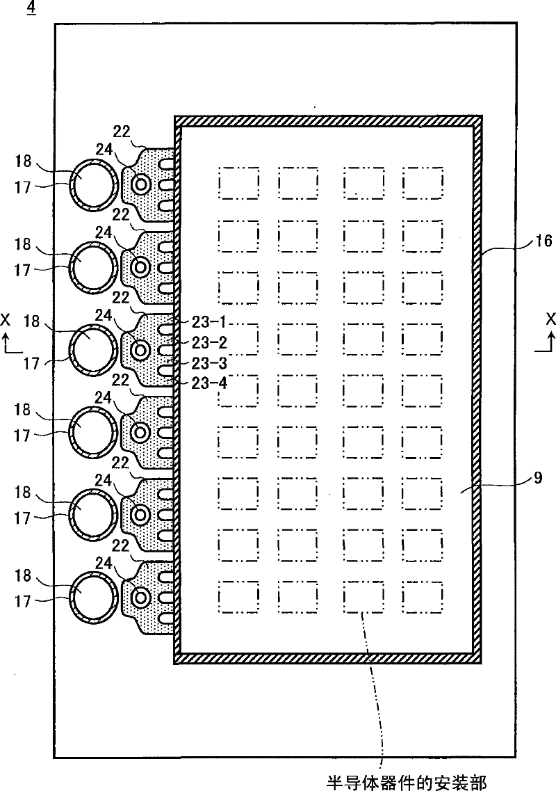
[0052] figure 1 is a schematic cross-sectional view of a resin sealing mold provided in a resin sealing apparatus used in a resin sealing method of an electronic component according to a first embodiment of the present invention. figure 1 That is to refer to the following Figure 2 to Figure 5 Cross-sectional view of line X-X in.
[0053] refer to figure 1 , The resin sealing mold of the first embodiment of the present invention includes an upper mold 1 , a lower mold 2 , a first middle mold 3 and a second middle mold 4 . The respective areas of the upper mold 1 , the lower mold 2 , the first middle mold 3 and the second middle mold 4 are substantially the same.
[0054] The upper mold 1 is fixed to an upper mold fixing portion 5 of the resin sealing apparatus. The lower mold 2 is fixed to a lower mold fixing portion 6 of the resin sealing apparatus. The first intermediate mold 3 is stacked on the lower mold 2 . The second intermediate mold 4 is stacked on the first inte...
no. 2 example
[0115] In the first embodiment of the present invention, the pot portion 18 (which is a single resin supply source) is provided in the lower mold 2 and the intermediate molds 3, 4 where the cavity forming portions 7 to 9 are formed. Resin is supplied from the pot-shaped portion 18 to the cavity forming portions 7 to 9 via the lower-mold runner portion 28 , the first middle-mold runner portion 25 , and the second middle-mold runner portion 22 , wherein the lower-mold runner portion The portion 28 , the first middle mold runner portion 25 , and the second middle mold runner portion 22 are resin passages communicating with the cavity forming portions 7 to 9 .
[0116] But the present invention is not limited to this example. The present invention is applicable to an example in which molten resin is independently supplied to each cavity forming portion of a stack mold.
[0117] Figure 13 is a first schematic cross-sectional view of a resin sealing mold provided in a resin seali...
no. 3 example
[0156] In the first and second embodiments of the present invention, the cavity forming portions 7 and 67 are formed in the lower molds 2 and 62 other than the first intermediate molds 3 and 63 and the second intermediate molds 4 and 64 . But the present invention is not limited to these examples. The present invention can be applied to a case where the cavity forming portion is not formed in the upper mold and the lower mold but formed only on the upper and lower surfaces of the intermediate mold sandwiched between the upper mold and the lower mold.
[0157] Figure 21 is a schematic cross-sectional view of a resin sealing mold provided in a resin sealing apparatus used in a resin sealing method of an electronic component according to a third embodiment of the present invention. Figure 22 for Figure 21 A plan view of the intermediate mold 103 is shown. Figure 21 is along Figure 20 Cross-sectional view of line X-X in.
[0158] Figure 21 , Figure 22 in, with Figu...
PUM
 Abstract
Description
Claims
Application Information
 - R&D
- Intellectual Property
- Life Sciences
- Materials
- Tech Scout
- Unparalleled Data Quality
- Higher Quality Content
- 60% Fewer Hallucinations
Browse by: Latest US Patents, China's latest patents, Technical Efficacy Thesaurus, Application Domain, Technology Topic, Popular Technical Reports.
© 2025 PatSnap. All rights reserved.Legal|Privacy policy|Modern Slavery Act Transparency Statement|Sitemap|About US| Contact US: help@patsnap.com


