Cutting insert

A technology of cutting inserts and inserts, applied in turning equipment, accessories of toolholders, tools for lathes, etc., can solve problems such as damage to accuracy and quality, unstable chip control, and low height, to prevent accuracy and quality. Damage, long-term stability and smoothing, the effect of suppressing the increase in cutting resistance

Active Publication Date: 2008-10-01
MITSUBISHI MATERIALS CORP
View PDF4 Cites 14 Cited by
  • Summary
  • Abstract
  • Description
  • Claims
  • Application Information

AI Technical Summary

Problems solved by technology

Therefore, the cutting oil cannot be sufficiently supplied to the front main cutting edge, especially the corner portion side, and the corner portion is prone to be damaged by the heat of the cutting edge, and sticking etc. are likely to occur depending on the material to be cut, and there are May damage the accuracy and quality of the groove wall surface or cut surface of the machined workpiece
[0007] On the other hand, when the cutting insert is sent out in the longitudinal direction and only grooving or parting of the workpiece is performed exclusively through the front main cutting edge, the chips generated by the front main cutting edge are in collision and sliding contact. While being on a pair of bumps, it is fed into the chip breaking pit, but if the chips continue to slide in this way, the bumps (nodules) will wear down and their height will become low, and eventually they will be worn off and disappear.
Therefore, chip control becomes impossible due to the wear of the bumps, so not only the life of the cutting insert is exhausted, but also the chip control becomes unstable while the bumps are worn down. , so it is difficult to perform smooth processing

Method used


Image

  • Cutting insert
  • Cutting insert
  • Cutting insert

Examples


Embodiment Construction

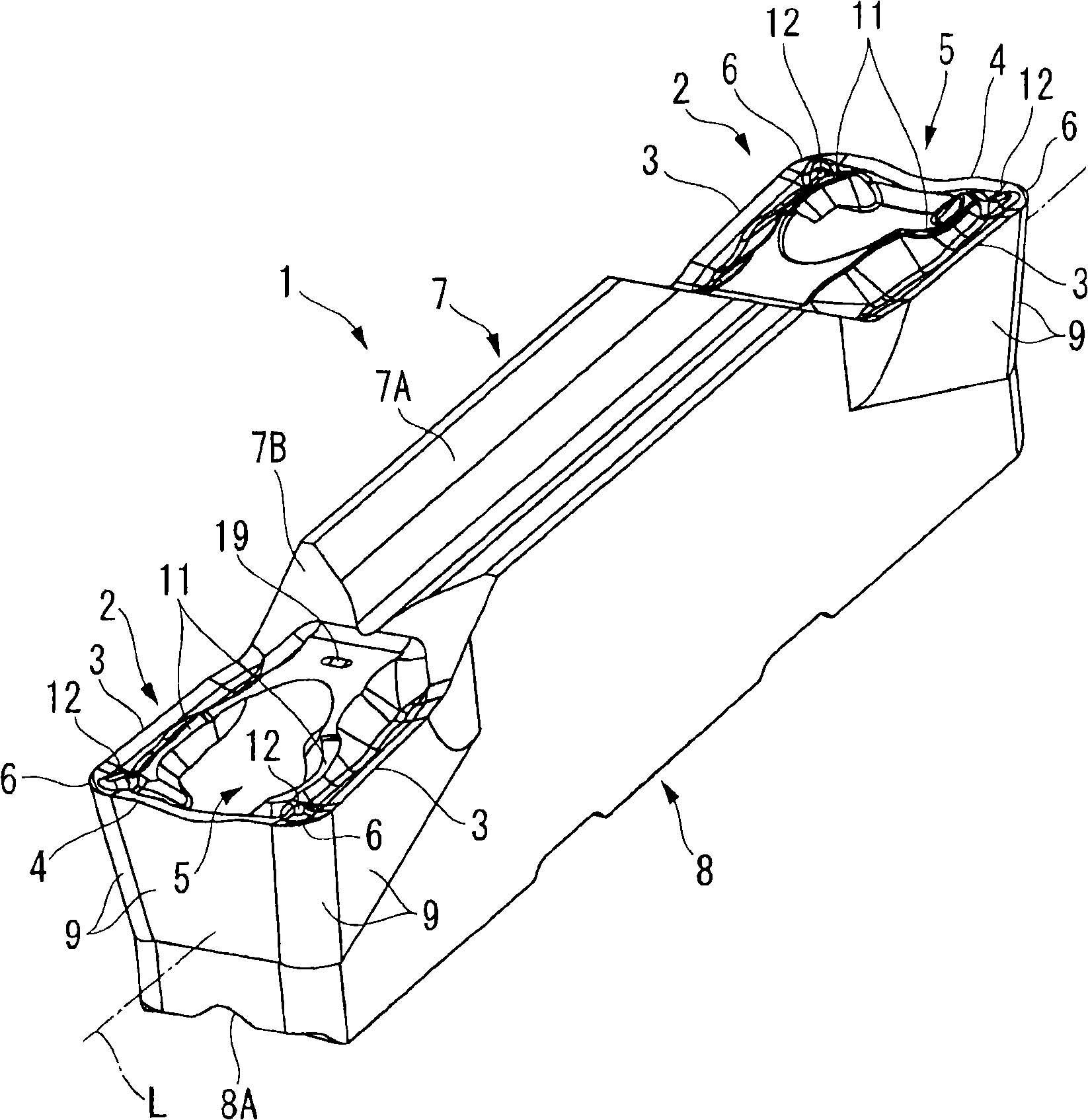
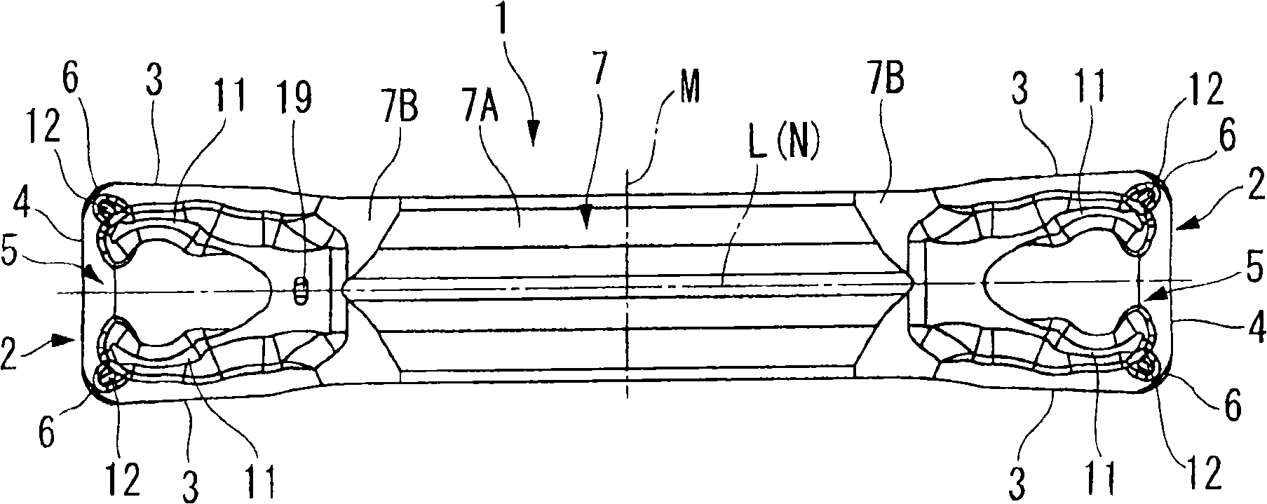
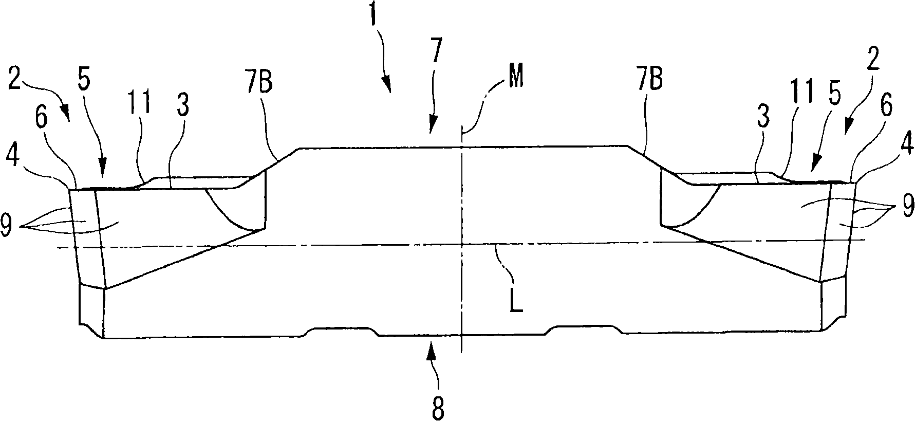
[0059] Figure 1 to Figure 8 It is a figure which shows 1st Embodiment of the cutting insert of this invention. In the present embodiment, the insert body 1 is formed of a hard material such as cemented carbide, and has a substantially square shaft shape (square column shape) extending along the axis L. As shown in FIG. The blade body 1 is formed approximately symmetrically with respect to a plane M which is orthogonal to the axis L and which is located in the length direction of the blade body 1 (direction of the axis L, Figure 2 ~ Figure 4 in the left and right directions) in the center. Furthermore, the blade main body 1 has a symmetrical shape with respect to the plane N as well. The plane N is orthogonal to the plane M and is located in the width direction of the blade body 1 ( figure 2 and Figure 4 in the up and down direction, in Figure 5 Middle is the left-right direction) center, including the axis L and in the thickness direction of the blade main body 1 ( ...


PUM


Abstract

A cutting insert having an insert body formed in a shaft-shape, wherein a cutting edge portion having a square rake face is formed on an end portion of the insert body, and wherein the rake face includes: a pair of side cutting edges extending in a longitudinal direction of the insert body; a front cutting edge extending in a transverse direction perpendicular to the longitudinal direction between each front end of the side cutting edges; a pair of protruded streaks extending toward each of corner portions at which each of the side cutting edges intersect the front cutting edge, and a projection which protrudes and is separated from the protruded streaks between front ends of the protruded streaks in the vicinity of the corner portion and the corner portion.

Description

technical field [0001] The present invention relates to a cutting insert used for grooving or cutting off a material to be cut in turning. This application claims Japanese Invention Patent Application No. 2007-091952 and No. 2007-094884 filed on March 30, 2007, and Japanese Invention Patent Application No. 2008-012974 filed on January 23, 2008 Priority, its content is introduced here. Background technique [0002] As such a cutting insert used in grooving or parting, for example, Japanese Unexamined Patent Publication No. 9-174308 proposes a cutting insert having a pair of convex blades extending substantially in the longitudinal direction on the top surface of the cutting head. strips, chip breaking pockets between the ribs, crease lines extending between the pocket portions at the front and rear locations of the chip breaking pockets, and positions configured to be included between the crease lines and A pair of protrusions (bulges) in the front concave part between the ...

Claims


Application Information

Patent Timeline
Patent Type & Authority Applications(China)
IPC IPC(8): B23B27/04
Inventor 长屋秀彦麻生典夫今井康晴
Owner MITSUBISHI MATERIALS CORP
Why Eureka
Try Eureka