Upper rigidity contact net electric subway integral elevating translational type interval partition door

A technology of rigid contact and overall lifting, which is applied in the direction of railway car body parts, wing leaf layout, stations, etc., can solve the problems of uneven compression and non-fixed value of the rubber strips at the door frames on both sides, and solve the problem of uneven rubber strips Compression, short conversion time, fast conversion effect

Active Publication Date: 2008-10-01
ENG DESIGN RES INST OF SECOND ARTILLERY PLA
View PDF0 Cites 6 Cited by
  • Summary
  • Abstract
  • Description
  • Claims
  • Application Information

AI Technical Summary

Problems solved by technology

[0003] The object of the present invention is to provide an overall lift-and-translate section partition door for the upper rigid catenary receiving electricity subway, which not only solves the problem of not disconnecting the catenary when closing the door, but also solves the problem of large height difference and large longitudinal slope in the sweeping width of the door leaf. and solve the problem of uneven compression of the rubber strips on both sides of the door frame caused by the excessive width of the door leaf; at the same time, because the installation position of the upper catenary has a certain offset relative to the center line of the line, and each The offset at the mileage of the personal defense section is not a fixed value, so it is required that the section partition door should adopt an adjustable structure when sealing the position of the upper catenary to ensure the airtight effect of the upper catenary

Method used


Image

  • Upper rigidity contact net electric subway integral elevating translational type interval partition door
  • Upper rigidity contact net electric subway integral elevating translational type interval partition door
  • Upper rigidity contact net electric subway integral elevating translational type interval partition door

Examples


Embodiment Construction

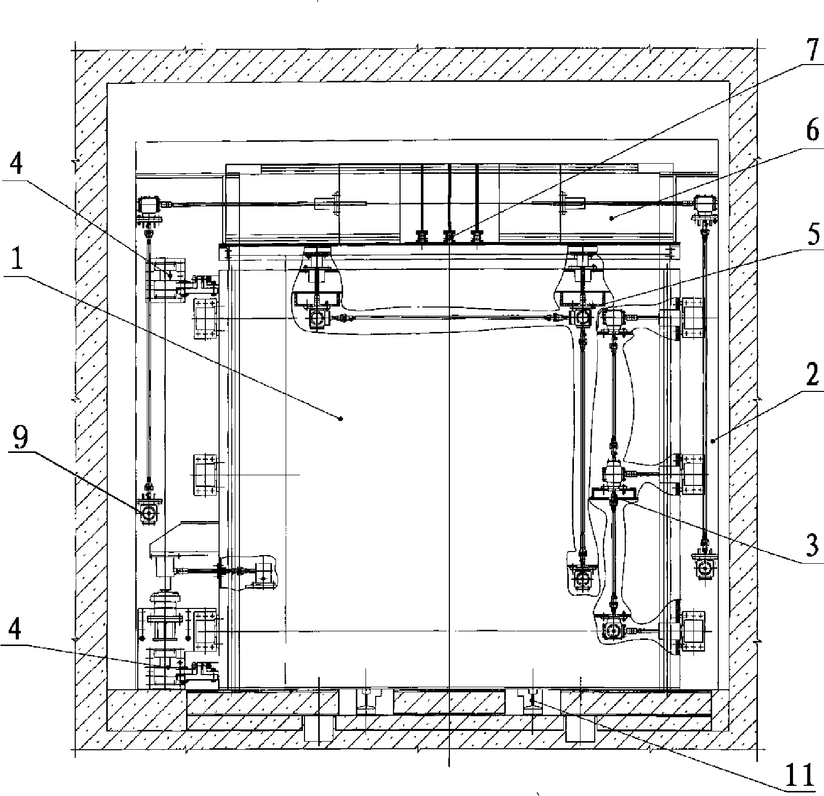
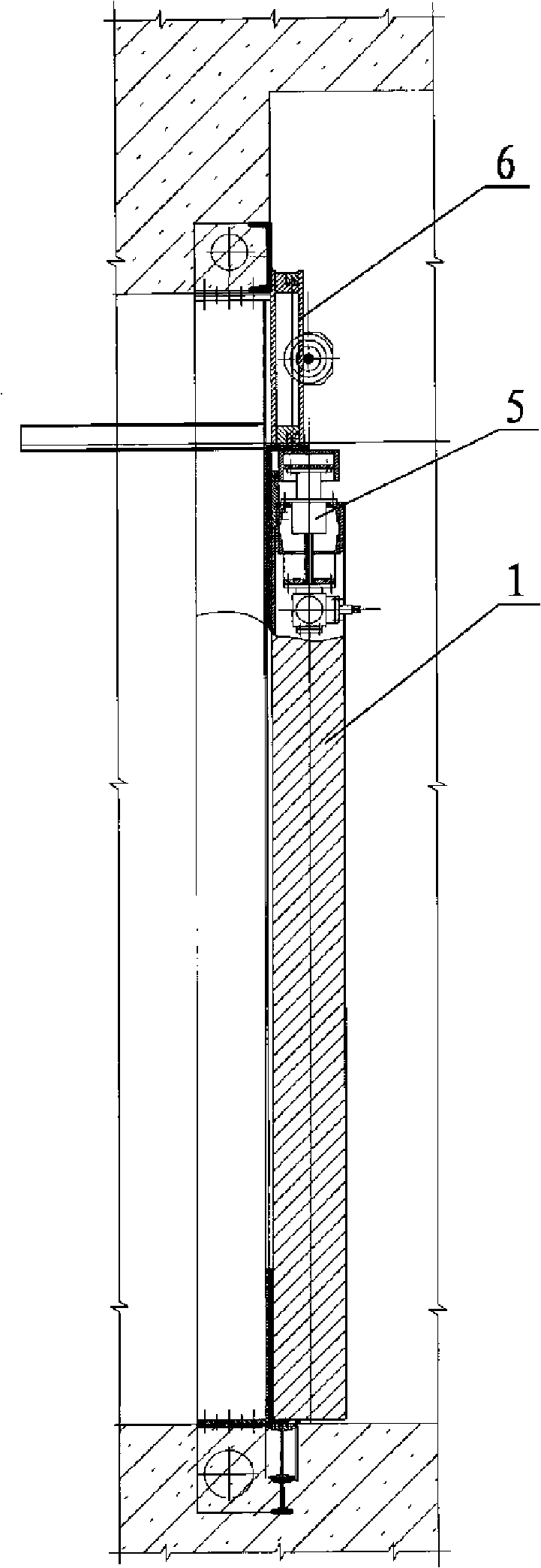
[0030] Examples see Figure 1-4 As shown, this upper rigid catenary electric receiving subway overall lifting and translation partition door includes the partition door leaf 1 above the track 11, the door frame 2, the hinge 4 and the locking device 3 connecting the above two, and the opening position Lock support. The door frame is a four-part splicing structure of upper, lower, left and right door frames.

[0031] An upper movable cover device 6 is provided at the junction between the inner surface of the partition door leaf 1 and the inner surface of the door frame 2, and an upper and lower sealing device 5 is installed on the upper part of the door leaf. When opening the door, first shake the handle of the upper movable cover device to move the left 63 and right movable cover 65 to the open position. At this time, enough insulation space has been reserved on both sides of the rigid catenary, and then lower the upper lifting sealing device 5. Then raise the door leaf as a ...


PUM


Abstract

The invention relate to an upper rigid centenary system electrical subway integral lifting translation type interval partition door, comprising a interval partition door leaf over a track, a door frame, a hinge connecting the door leaf with the door frame and a locking device, the joint between the inside surface upper edge of the interval partition door leaf and the inside surface of the door frame is equipped with an upper part movable cover plate device. The lower surface of the upper part movable cover plate device and the upper surface of an upper lifting sealing device form a sealing abutted surface. The upper part of the upper lifting sealing device, relative to a rigid catenary system and the lower surface of a wire, is fixed with a profile modeling sealing rubber block. By using an integral lifting translation type hinge and setting the upper lifting sealing device, closing in place is realized without the wire being disconnected, the transformation from peacetime to wartime is fast. In addition, the upper part movable cover plate device and the upper lifting sealing device employ profile modeling sealing structure, which effectively solves the closing difficulty of the upper rigid catenary system, the structure is simple, and the closing property is reliable.

Description

(1) Technical field [0001] The invention relates to a subway compartment partition door. (2) Background technology [0002] According to the relevant provisions of my country's "Civil Air Defense Law", the needs of civil air defense must be taken into account during the construction of subway projects. The subway is built underground, which itself has certain protection capabilities. If the needs of civil air defense are taken into account during construction, unified planning, design, and construction, and key constructions of key parts and important facilities are done, the subway project can be used as a city's security system at ordinary times. The underground traffic trunk line is an important evacuation trunk road for urban air defense during wartime, and can also be used as a personnel shelter to ensure the safety of personnel and equipment during the expected nuclear, chemical, and conventional weapon attacks and secondary urban disasters after the attack , thus gre...

Claims


Application Information

Patent Timeline
Patent Type & Authority Applications(China)
IPC IPC(8): E06B5/10E06B3/32B61B1/02
Inventor 胡玉镜张伟刚刘斌生谢育新闫梦扬邵玮
Owner ENG DESIGN RES INST OF SECOND ARTILLERY PLA
Why Eureka
Try Eureka