
Compression bandage

A technique of compressing bandages, bandages, applied in the direction of chest bandages, abdominal bandages, breast bandages, etc., to achieve the effect of reducing the risk of forming creases and shrinkage

Active Publication Date: 2008-10-01
多里特亚·瑙曼
View PDF0 Cites 2 Cited by
  • Summary
  • Abstract
  • Description
  • Claims
  • Application Information

AI Technical Summary

Problems solved by technology

But the disadvantage is that the compression pressure can hardly be changed and different size classes of bras have to be prepared for patients of different sizes

Method used


Image

  • Compression bandage
  • Compression bandage
  • Compression bandage

Examples


Embodiment Construction

[0032] The figures show in detail:

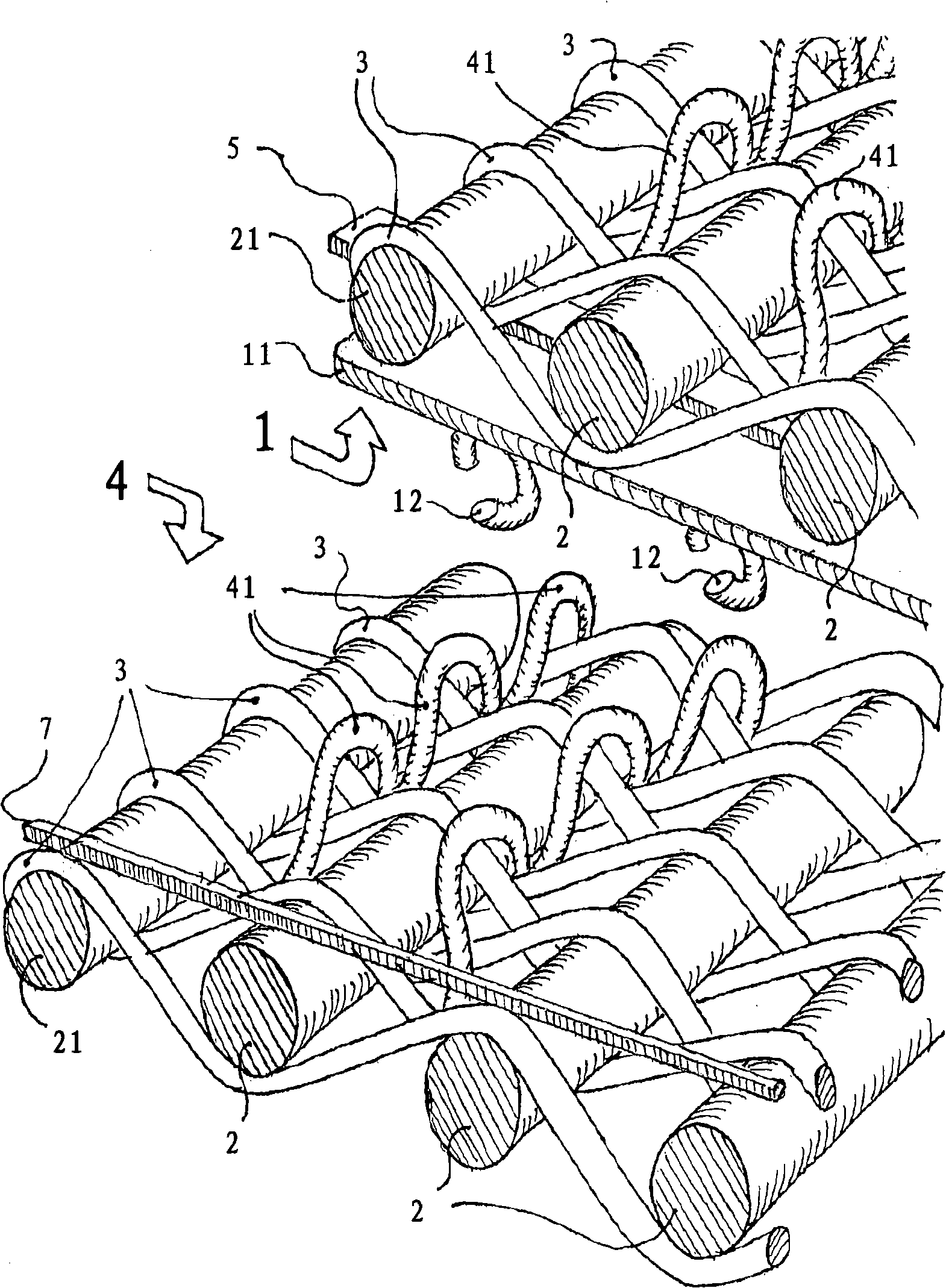
[0033] figure 1 A cross section depicting a detail of the fabric of a compression bandage of the present invention. Individual elastic fibers 2 can be seen in transverse section, which extend in the longitudinal direction of the bandage. Each supporting fiber 3 is wound around each elastic fiber 2 in the transverse direction. The individual loops 41 are woven into the fabric comprising the support fibers 3 and the elastic fibers 2 . exist figure 1 The other end of the compression bandage can be seen in the top half. Some loops 41 are also shown on its soft pile side 4 , but not in all numbers at all intersections of the fabric for the sake of clarity.

[0034] The hook side 1 is opposite the soft nap side 4 of the compression bandage. figure 1 As can be seen in , why it has this name: the hook strip 11 is fastened on one end on this side. According to the prior art, the hook strip 11 comprises a supporting fabric, which runs parallel...


PUM


Abstract

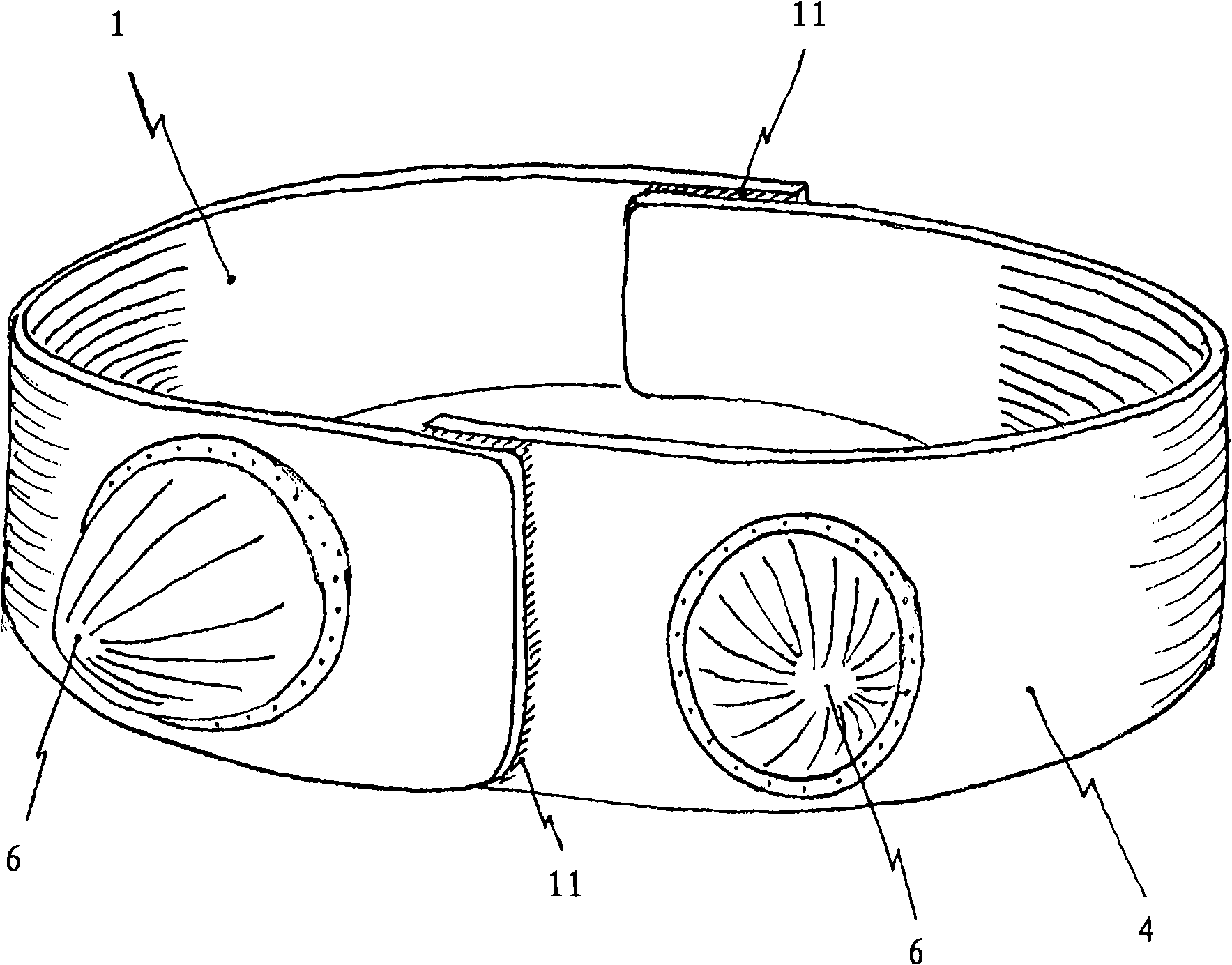
The invention relates to a compression bandage in the form of an elongated rectangle made of a textile fabric on which a hook strip (11) is fastened along a narrow side on a small portion of a lateral face, the hook side (1). The fabric contains elastic threads (2) running in a longitudinal direction and, in the transversal direction, consists of nearly inelastic supporting threads (3).; The invention is characterized in that the spring constant in the longitudinal direction ranging, in the order of magnitude of 0.3 (three-tenths) to 3 (three) Newtons per centimeter of longitudinal stretching and per meter length and per decimeter width of the compression bandage, and uniformly distributed small loops (4) made of soft threads are interwoven over the entire area of the lateral face opposite the hook strip, the coating side, these small loops being oriented approximately perpendicular to the lateral face, are complementary in size and distance from one another to the hooks of the hook strip, and with which, together with the hook strip, a releasable hook and loop closure can be formed.

Description

technical field [0001] The invention relates to a compression bandage in the form of an elongated rectangle made of a woven fabric on which a strip of hooks is fastened along a narrow side on a small part of one side, the hook side, wherein the fabric comprises longitudinally extending Elastic fibers, and in the transverse direction are composed of almost inelastic supporting fibers. Background technique [0002] When surgery in the breast area, such as when the shape of the breast changes or in heart surgery, leaves large internal wounds that are held together by an external compression bandage until they have developed sufficient intrinsic stability through treatment until. Otherwise, cavities will form, with the result that the healing process is delayed and scar formation is increased. [0003] Especially when plastic surgery is performed on the breast, scars are undesirable. According to the prior art, therefore, a bandage is placed around the patient's breast after ...

Claims


Application Information

Patent Timeline
Patent Type & Authority Applications(China)
IPC IPC(8): A61F13/14
CPCA61F13/145
Inventor 多里特亚·瑙曼
Owner 多里特亚·瑙曼
Learn More