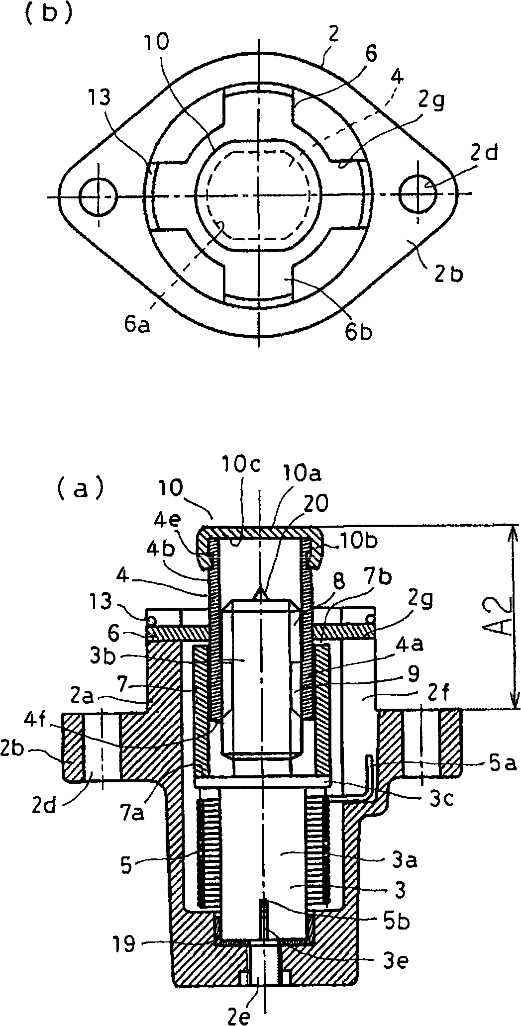
Tensioner
A technology for tensioning devices and shaft components, applied in the direction of transmission devices, belts/chains/gears, mechanical equipment, etc., can solve problems such as easy fixation, achieve a simple and compact structure, and ensure normal operation
- Summary
- Abstract
- Description
- Claims
- Application Information
AI Technical Summary
Problems solved by technology
Method used
Image
Examples
Embodiment approach 1
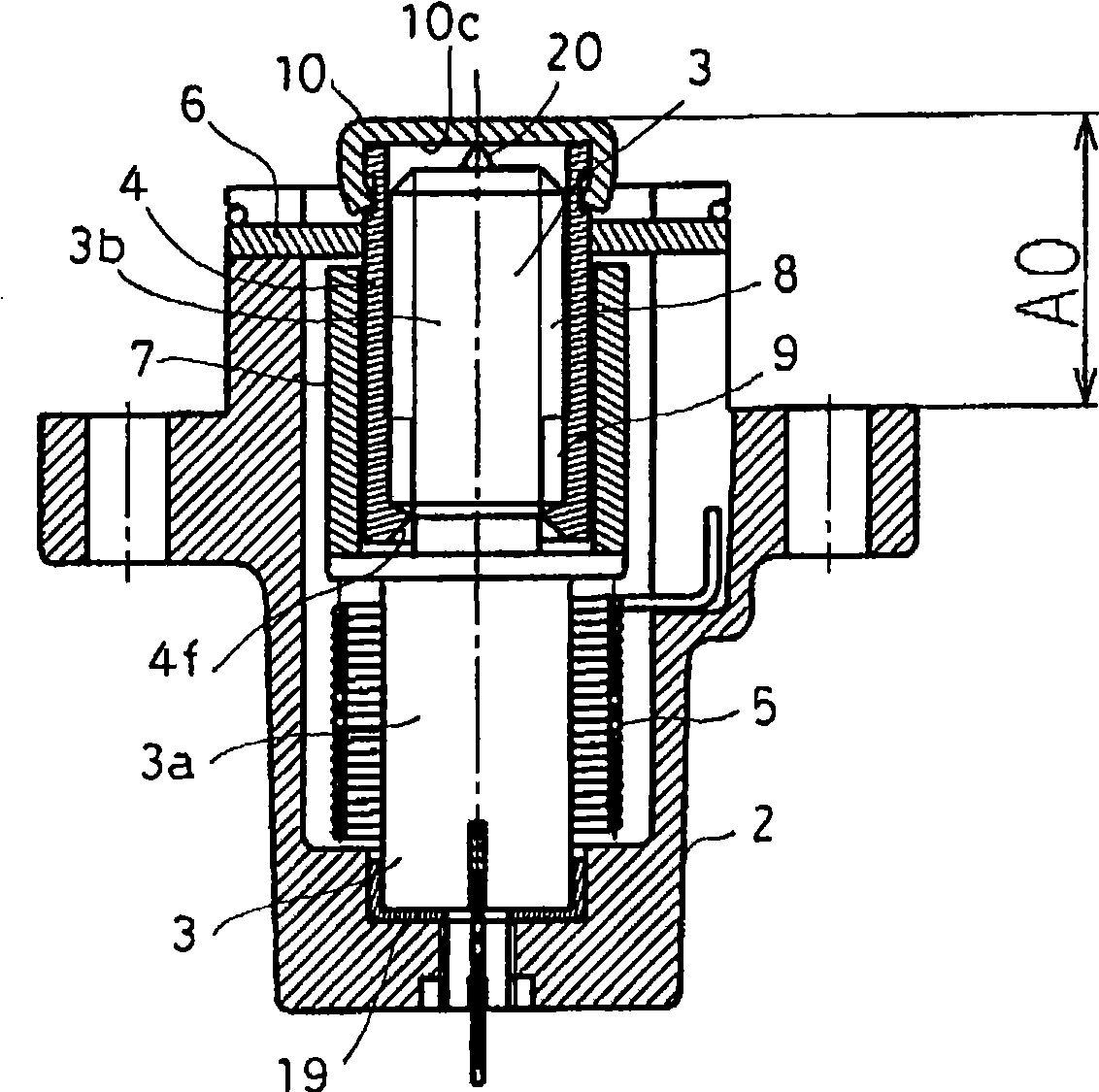
[0063] figure 1 is a longitudinal sectional view showing the tensioner according to Embodiment 1 of the present invention, figure 2 It is a longitudinal sectional view of the tensioning device in the fully retracted state. The tensioner of this embodiment roughly includes a housing 2, a first shaft member 3 as a rotating member, a second shaft member 4 as an advancing member, a torsion spring (elastic member) 5, a bearing 6, a spacer 7, these parts and Figure 7 The existing tensioner shown is substantially the same.
[0064] The housing 2 is shaped substantially in a bottomed cylindrical shape having a flange portion 2b in the middle of the cavity 2a. Furthermore, a storage hole 2c extending to the front end portion in the axial direction (propelling direction) is formed inside the cavity 2a. The front end portion of the housing hole 2c is open, and an assembly of the first shaft member 3, the second shaft member 4, the torsion spring 5, and the spacer 7 is housed in th...
Embodiment approach 2
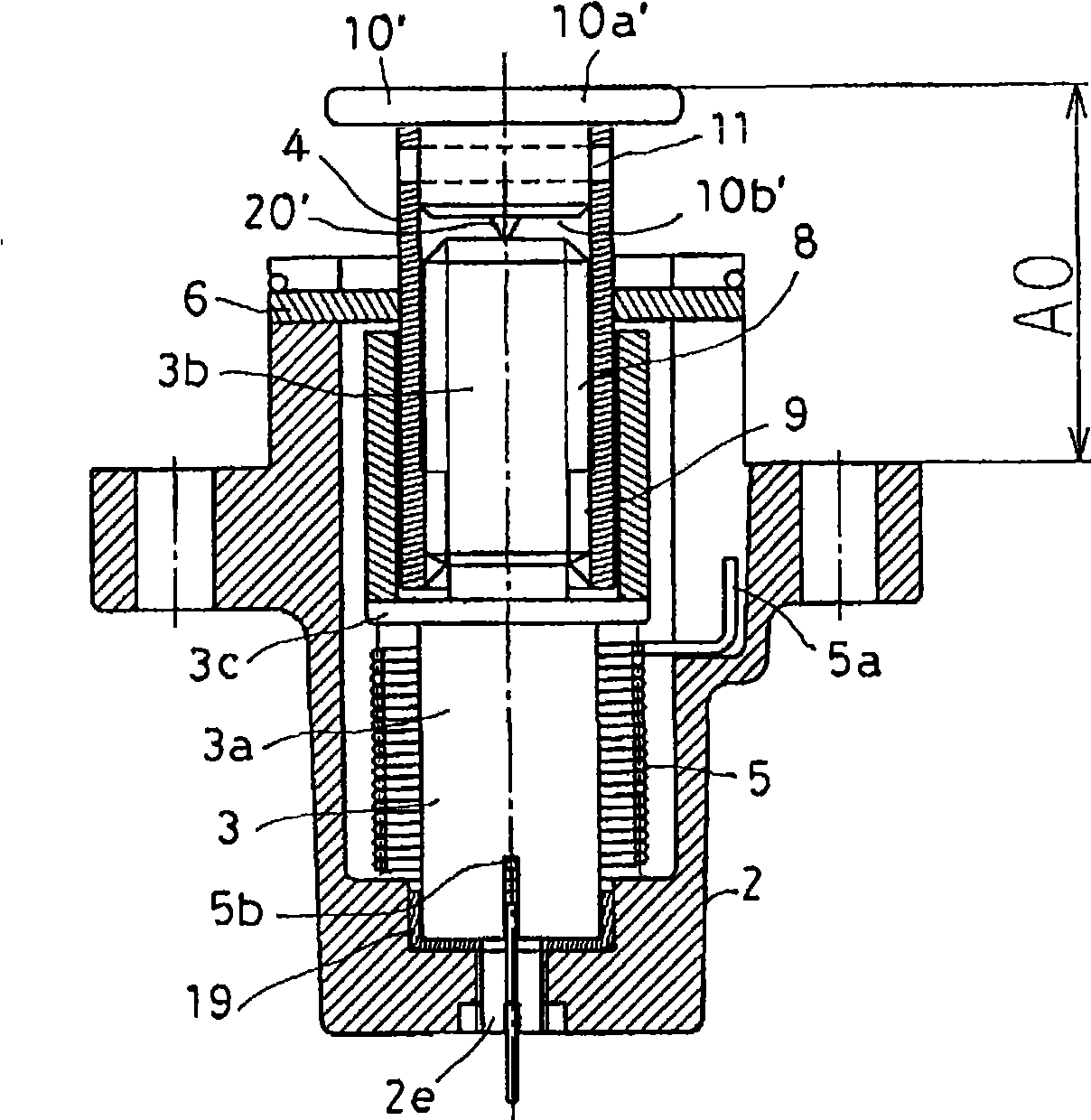
[0086] image 3 It is a longitudinal sectional view showing the tensioner according to Embodiment 2 of the present invention.
[0087] In this embodiment, the front pointed contact portion 20 is removed from the front end surface of the first shaft member 3 in Embodiment 1, and the front pointed contact portion 20' is provided on the front end member 10' side, so The configuration is the same as that of Embodiment 1 except that the shape of the tip member 10' is different.
[0088] The front end part 10' is composed of a head part 10a' and a foot part 10b', and the head part 10a' covers the front end part of the cylindrical part 4b of the second shaft part 4, and the leg part 10b' is inserted into the front end part of the cylindrical part 4b. In the state where the spring pin (pin) 11 is pressed in, the separation of the leg portion 10b' from the cylindrical portion 4b is prevented, so that the front end member 10' is fixed to the cylindrical portion 4b. A contact portion 2...
Embodiment approach 3
[0093] Figure 4 It is a longitudinal sectional view showing the tensioner according to Embodiment 3 of the present invention. In this embodiment, the front pointed contact portion 20 ′ of the front end member 10 ′ in Embodiment 2 is removed, and is provided between the rear end 4 f of the second shaft member 4 and the stepped portion 3 c of the first shaft member 3 . Therefore, other configurations of the bearing member 30 such as a thrust bearing are basically the same as those of the second embodiment.
[0094] Therefore, when the second shaft member 4 retracts to the fully retracted state (A0 position), the rear end 4f of the second shaft member 4 is in a state of abutting against the bearing member 30 . At this time, the inner side of the leg portion 10b' of the front end member 10' is not in contact with the front end surface of the first shaft member 3 with only a slight gap, and the second shaft member 4 cannot retreat further from the protrusion dimension A0.
[009...
PUM
 Abstract
Description
Claims
Application Information
 - R&D
- Intellectual Property
- Life Sciences
- Materials
- Tech Scout
- Unparalleled Data Quality
- Higher Quality Content
- 60% Fewer Hallucinations
Browse by: Latest US Patents, China's latest patents, Technical Efficacy Thesaurus, Application Domain, Technology Topic, Popular Technical Reports.
© 2025 PatSnap. All rights reserved.Legal|Privacy policy|Modern Slavery Act Transparency Statement|Sitemap|About US| Contact US: help@patsnap.com


