Filter arrangement

A filter and fuel cell technology, applied in the fields of dispersed particle filtration, electrochemical generators, chemical instruments and methods, etc., can solve problems such as limited design space, and achieve the effect of simple assembly and light weight

Active Publication Date: 2008-10-01
CARL FREUDENBERG KG
View PDF0 Cites 10 Cited by
  • Summary
  • Abstract
  • Description
  • Claims
  • Application Information

AI Technical Summary

Problems solved by technology

However, the available design space is limited, especially for compact fuel cells

Method used


Image

  • Filter arrangement
  • Filter arrangement
  • Filter arrangement

Examples


Embodiment Construction

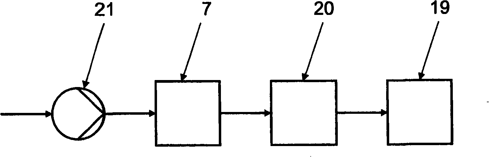
[0022] figure 1 A filter device 7 for purifying the fuel cell intake air entering the fuel cell 19 is shown, which filter device 7 is thus installed in the intake air flow of the fuel cell 19 . Especially for PEM fuel cells, if a humidifier 20 is provided in the intake air flow, the filter device 7 can be installed before the humidifier 20 to supply the humidifier 20 with purified intake air. In this case, the filter device 7 can be arranged upstream and / or downstream of the air delivery device 21 for delivering the intake air flow.

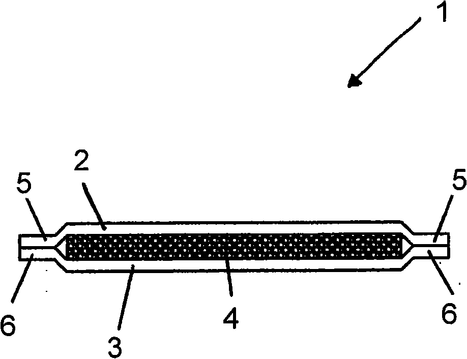
[0023] figure 2 The filter 1 installed in the filter device is shown. The filter 1 consists of two layers of first filter media 2, 3 and a layer of second filter media 4 mounted between the two layers of first filter media 2, 3, thus forming a sandwich-type design of the filter 1 . The filter media 2 , 3 , 4 are designed flat, the first filter medium 2 , 3 having a larger area than the second filter medium 4 . Thus, the edges 5 , 6 of the f...


PUM


Abstract

Filter arrangement (7) for cleaning the fuel cell intake air comprising at least one filter (1 ) of the at least two layers of a first filter medium (2, 3) and at least one additional layer of a second filter medium (4) whereby the second filter medium (4) is embedded between the first filter media (2, 3), and these first filter media (2, 3) are attached to the mutually opposing edge sections (5, 6) and comprising a housing (8) which comprises at least one top part (9) and one bottom part (10), whereby the top part (9) and the bottom part (10) each have a flange (11 , 12) and whereby the edge sections (5, 6) of the filter (1 ) are arranged between the flanges (11 , 12).

Description

technical field [0001] The invention relates to a filter device for purifying the intake air of a fuel cell. Background technique [0002] Fuel cells, especially PEM fuel cells, require that the intake air be free of corrosive elements for optimum efficacy and long-term durability. Corrosive elements are particulate and gaseous particles. Inscribed particles or abrasive particles or corrosive gases from system components arranged upstream such as air delivery equipment or corrosive gases can accumulate inside the fuel cell and can damage various parts such as gas passages, air diffusion layers, catalysts or MEA for optimum functionality. Corrosive elements can cause these components to wear out prematurely. In order to prevent particles from being entrained into the fuel cell, a filter is used to clean the intake air of the fuel cell. However, the available design space is limited, especially for compact fuel cells. Contents of the invention [0003] It is an object o...

Claims


Application Information

Patent Timeline
Patent Type & Authority Applications(China)
IPC IPC(8): H01M8/06B01D46/12H01M8/0662
CPCY02E60/50
Inventor R·卡芬贝格尔V·许克尔D·欣腾朗M·迈尔赫费尔
Owner CARL FREUDENBERG KG
Why Eureka
Try Eureka