Plate-shaped heating panel in which connecting members are fastened by bolts and nuts

a technology of connecting members and plates, applied in the field of plate-shaped heating panels, can solve the problems of increasing overhaul costs, affecting the efficiency of heating panels, and prolonging construction time, so as to reduce fuel costs, eliminate complicated piping work, and high heating efficiency

Inactive Publication Date: 2006-12-05
LG CHEM LTD
View PDF13 Cites 10 Cited by
  • Summary
  • Abstract
  • Description
  • Claims
  • Application Information

AI Technical Summary

Benefits of technology

[0005]In order to solve the problems of the conventional wet heating system as described above, a dry heating panel, made of concrete, a synthetic resin or yellow clay, was developed. The dry heating panel has a pipe for carrying heating water embedded therein or is provided with grooves or fixing members for inserting the pipe for carrying heating water. The dry heating panel is an assembled heating panel, and has advantageous effects in that the construction of the heating system may be completed by simply assembling previously produced pieces of the dry heating panel, thereby reducing the construction time, and simplifying maintenance and overhaul operations thereof. However, the dry heating panel has problems in that, since it adopts a line heating structure in which radiation heat is mainly concentrated where the pipe for carrying heating water is located, generating a severe temperature variation in the heating system, the dry heating panel is ineffective in view of heating efficiency, and in that, since the pipe itself is made of metal or a synthetic resin, it is expensive, resulting in increased construction costs. Furthermore, thermal loss may occur due to piping, and dewing may occur on the surface of the pipe, thereby wetting the panel.
[0006]In order to solve the problems of the conventional dry heating panel described above, as disclosed in U.S. Pat. No. 5,080,166 and Korean patent application Laid-open publication No. 2002-95733, a plate-shaped heating panel provided with an inner fluid pathway for allowing the heating water to flow therethrough was developed. Compared with the dry type heating system adopting the line heating structure, the plate-shaped heating panel having the inner fluid pathway therein adopts a plane heating structure in which the heating water flows not in a local area but in an overall area of panels, so that it provides very high heating efficiency, resulting in reduction of fuel expenses, and so that the pipe is not required for the structure of the plate-shaped heating panel, thereby eliminating a complicated piping work and reducing the expenses for piping. Additionally, the plate-shaped heating panel is not subjected to the thermal loss and dewing, which usually occur on the surface of the pipe in the structure of the dry heating panel, and allows the weight of the panel to be reduced. Furthermore, the plate-shaped heating panel is very easy to construct and repair.
[0007]Conventionally, the plate-shaped heating panel with an inner fluid pathway formed therein was formed by way of blow molding, as also known as hollow molding. The blow molding is a molding method which forms a hollow product by blowing air into a separating mold, in which molten thermoplastic forming material is inserted and then softened with heat.
[0008]Conventionally, upon manufacturing the plate-shaped heating panel by way of the blow molding, a thermoplastic resin is pushed in an extrusion die, and hot air is blown into the resin, forming a cylindrical-shaped resin. Then, the resin is compressed by molds at both sides, thereby forming a heating panel with an inner fluid pathway formed therein.
[0009]The inner fluid pathway adjacent to an inlet or an outlet of the heating panel produced as described above is thinned due to a strong pressure of the hot air, and an angle of a notch (which is an edge submerging a small angle between symmetrical lines) is further decreased, causing stress to concentrate on the notch, resulting in reduction of the pressure resistance of the heating panel.
[0010]Accordingly, in the case where heating water of a predetermined pressure is passed through the heating panel, such a stress concentration around the inlet and outlet can form a crack around the inlet or the outlet, leading to damage of the inlet and outlet of the heating panel, and separation of connecting members of the heating panel. If any part of the heating panel is damaged, the separation of the connecting member affects the entire heating panel, resulting in separation of the heating panel.

Problems solved by technology

However, such a wet type heating system has a lower heating efficiency, resulting in large thermal losses, and requires lengthy concrete curing, resulting in extended construction time.
Furthermore, upon leakage of water from the pipe, a mortar layer of the heating system must be broken for repair, thereby impeding easy overhaul while increasing overhaul costs.
However, the dry heating panel has problems in that, since it adopts a line heating structure in which radiation heat is mainly concentrated where the pipe for carrying heating water is located, generating a severe temperature variation in the heating system, the dry heating panel is ineffective in view of heating efficiency, and in that, since the pipe itself is made of metal or a synthetic resin, it is expensive, resulting in increased construction costs.
Furthermore, thermal loss may occur due to piping, and dewing may occur on the surface of the pipe, thereby wetting the panel.
The inner fluid pathway adjacent to an inlet or an outlet of the heating panel produced as described above is thinned due to a strong pressure of the hot air, and an angle of a notch (which is an edge submerging a small angle between symmetrical lines) is further decreased, causing stress to concentrate on the notch, resulting in reduction of the pressure resistance of the heating panel.
Accordingly, in the case where heating water of a predetermined pressure is passed through the heating panel, such a stress concentration around the inlet and outlet can form a crack around the inlet or the outlet, leading to damage of the inlet and outlet of the heating panel, and separation of connecting members of the heating panel.
If any part of the heating panel is damaged, the separation of the connecting member affects the entire heating panel, resulting in separation of the heating panel.

Method used


Image

  • Plate-shaped heating panel in which connecting members are fastened by bolts and nuts
  • Plate-shaped heating panel in which connecting members are fastened by bolts and nuts
  • Plate-shaped heating panel in which connecting members are fastened by bolts and nuts

Examples


Embodiment Construction

[0021]Preferred embodiments of the present invention will be described in detail with reference to the drawings.

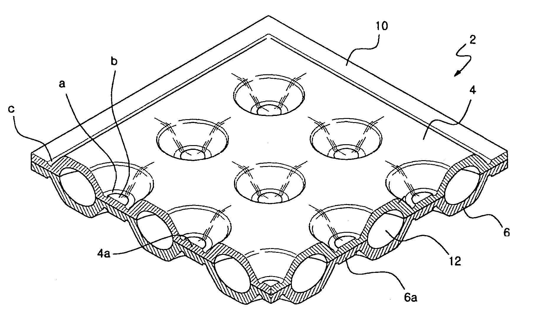
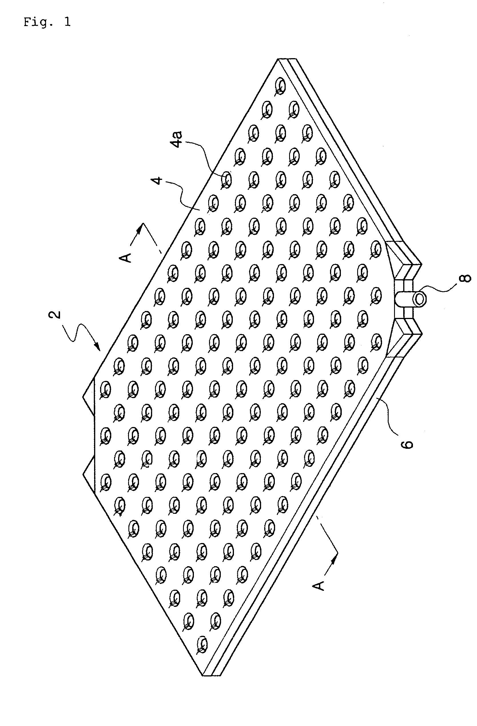
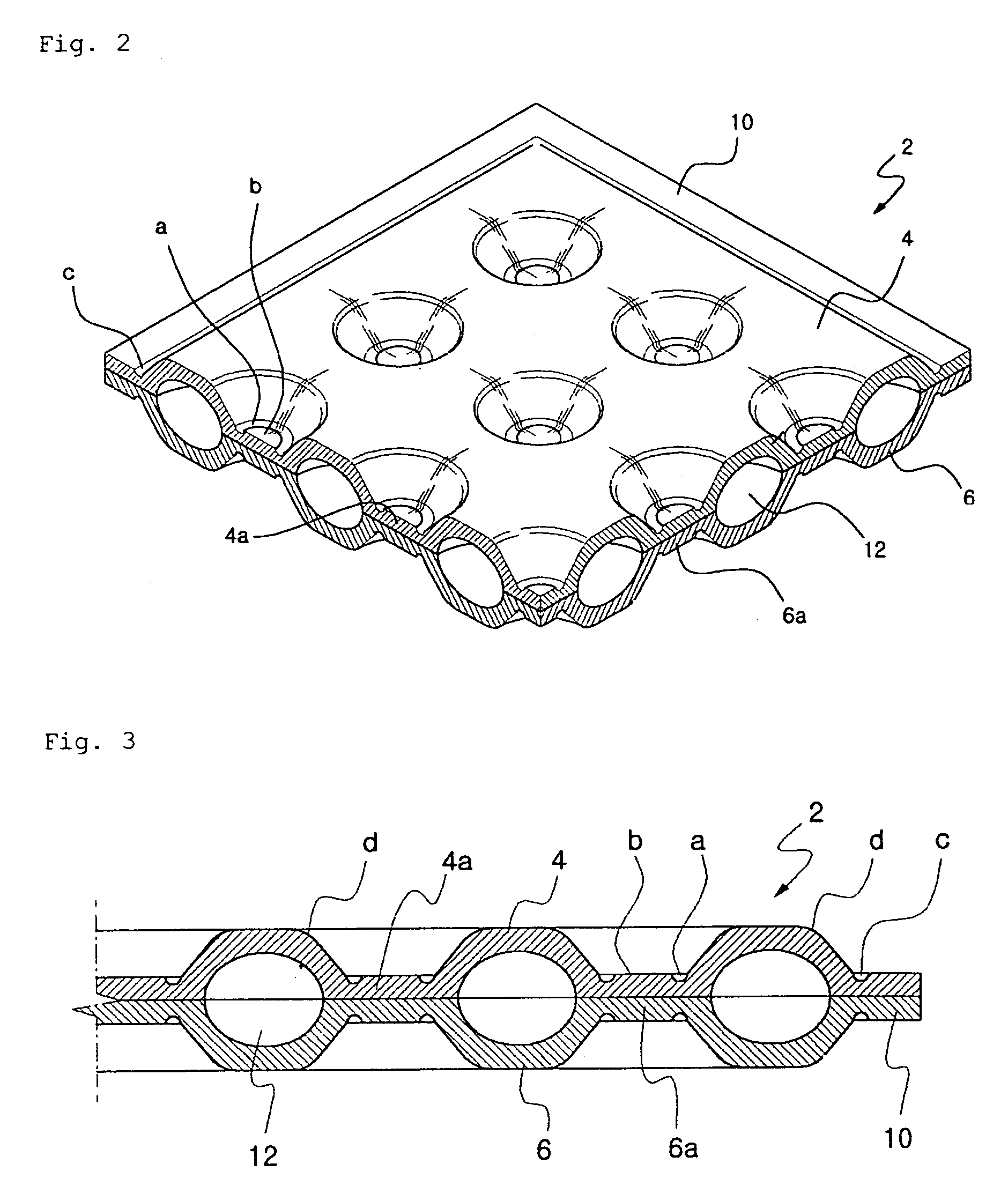
[0022]FIG. 1 is a perspective view illustrating a plate-shaped heating panel according to one embodiment of the present invention, and FIG. 2 is an enlarged cut-away view of FIG. 1. A heating panel 2 of the present invention comprises upper and lower plates 4 and 6 integrally formed to face each other, forming an inner fluid pathway 12 in which heating fluid flows. In order to allow easy manufacturing and forming, the heating panel 2 is made of a thermoplastic material, and has a flat plate shape in order to maximize surface contact with the floor (it is also applicable to a wall or a ceiling) of a room such that the heating fluid may contact the floor of the room over a larger area.

[0023]As shown in FIG. 1, the heating panel 2 has a rectangular structure with a pair of long sides and a pair of short sides. However, for easier continuous arrangement of the heating panels i...


PUM

PropertyMeasurementUnit
pressure resistanceaaaaaaaaaa
heating efficiencyaaaaaaaaaa
temperatureaaaaaaaaaa

Abstract

Disclosed herein is a plate-shaped heating panel having connecting members fastened to each other by means of bolts and nuts. The heating panel comprises upper and lower plates integrally formed to face each other so as to form an inner fluid pathway in which heating water flows, a plurality of connecting members, each symmetrically extending from the upper and lower plates toward the lower and upper plates, respectively, and connecting the upper and lower plates to each other, the inner fluid pathway formed inside of the plate by means of the plurality of connecting members, and two fluid communication portions for supplying and discharging the heating water, wherein one or more connecting members adjacent to the fluid communication portions are punctured such that punctured portions of the connecting members are fastened to each other by means of bolts and nuts. Accordingly, a bonding strength of the heating panel is enhanced, and even though the crack is generated, the crack is forced to change in its progressing direction and is prevented from spreading, thereby enhancing the pressure resistance of the heating panel.

Description

BACKGROUND OF THE INVENTION[0001]1. Field of the Invention[0002]The present invention relates to a plate-shaped heating panel with an inner fluid pathway formed therein, and more particularly to a heating panel, which has connecting members fastened to each other by means of bolts and nuts, thereby enhancing pressure resistance.[0003]2. Description of the Related Art[0004]Generally, a heating system, having been applied to residential buildings, such as houses, villas, and apartments, employs a structure involving a wet heating process, in which a pipe is laid under a flooring material of a room in a building and supplied with heating fluid, such as heating water, thereby heating the room of the building. However, such a wet type heating system has a lower heating efficiency, resulting in large thermal losses, and requires lengthy concrete curing, resulting in extended construction time. Furthermore, upon leakage of water from the pipe, a mortar layer of the heating system must be b...

Claims


Application Information

Patent Timeline
Patent Type & Authority Patents(United States)
IPC IPC(8): F28F3/12
CPCF24D3/16F24D3/142F24D3/127Y10T29/49366F28F3/044F28D1/0308Y02B30/00F24D3/12
Inventor KANG, SE-CHANGPARK, JANG-SEOKCHAE, KYOUNG-MYOUNGHAN, MIN-SOOPARK, SEONG-CHANHWANG, SUNG-SEOCK
Owner LG CHEM LTD
Why Eureka
Try Eureka