Cutter-head of machine for making furrows in farmland

A trencher and cutter head technology, applied in agricultural machinery and implements, agriculture, farming implements and other directions, can solve the problems of poor reliability, large load, easy damage to the keyway of the single-key shaft, etc., and achieves convenient disassembly and assembly and simple structure. , the effect of easy processing

Inactive Publication Date: 2011-05-04
葛玉明
View PDF1 Cites 7 Cited by
  • Summary
  • Abstract
  • Description
  • Claims
  • Application Information

AI Technical Summary

Problems solved by technology

The cooperation between the cutter head shaft and the hole on the cutter head of the existing ditching machine uses a common single key or spline to transmit the torque. This structure has the following disadvantages: 1. Although compared with the double cantilever ditching machine, the The disassembly and assembly of the cutter head of this kind of single cantilever trencher is relatively convenient, but it is still difficult to disassemble the cutter head from the cutter head shaft
2. The cutter head is easy to install in the opposite direction
In the existing technology, the radial size and shape of the matching section between the shaft and the shaft hole are consistent, and the holes on the cutter head can be assembled no matter whether they are front or back, and it is easy to cause reverse assembly mistakes in the rush during the busy season. If the cutter head is installed upside down, it will cause the back of the cutter and the soil to cut and the load will be too heavy to make ditching impossible
3. Poor reliability
First, if the keyway of the single-key shaft has a large gap, it is easy to be damaged; second, the single-key shaft must have a key, and like the spline shaft, it also needs a flat pad to press on the outside of the cutter head. It is very small, and it will be mixed with the soil after falling to the ground, and it is easy to be lost during dismantling and installation in the field, which will affect the use and delay the farming time

Method used


Image

  • Cutter-head of machine for making furrows in farmland
  • Cutter-head of machine for making furrows in farmland
  • Cutter-head of machine for making furrows in farmland

Examples


Embodiment 1

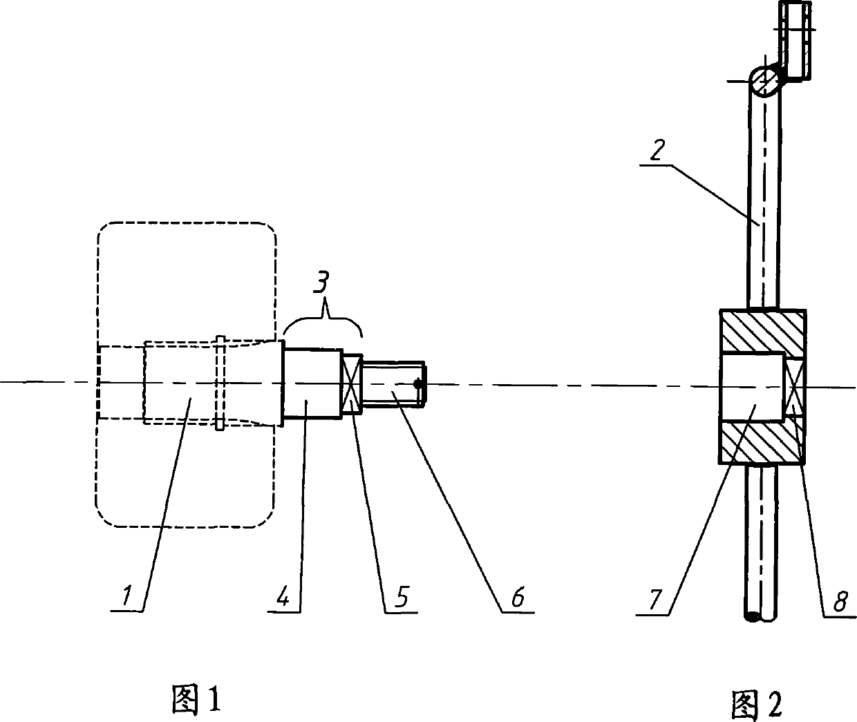
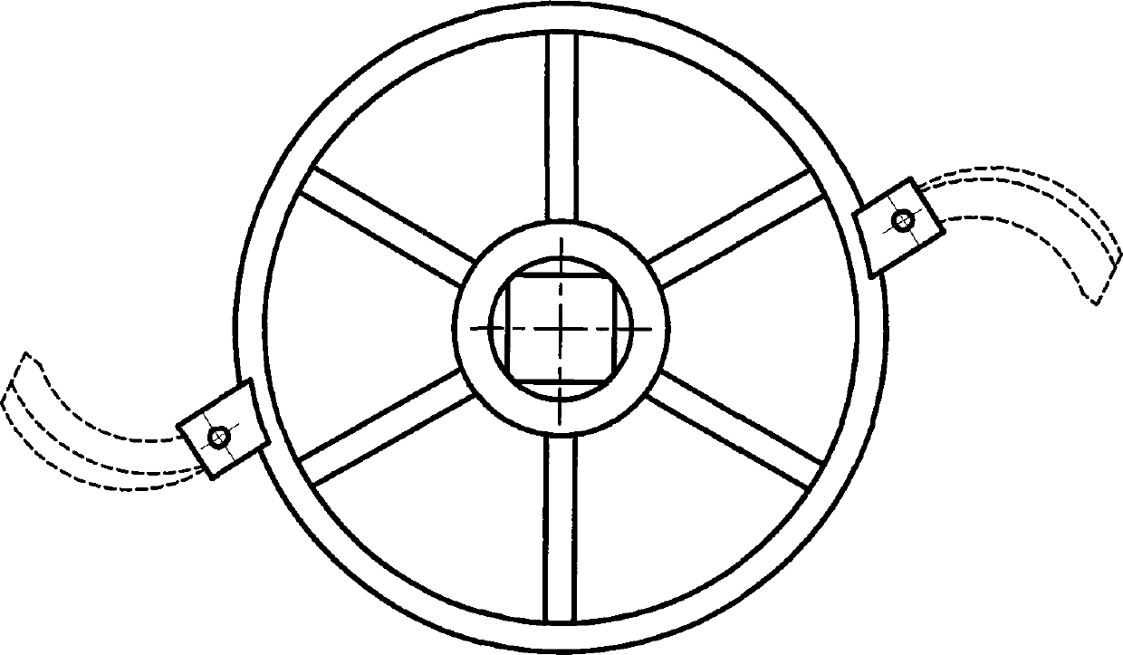
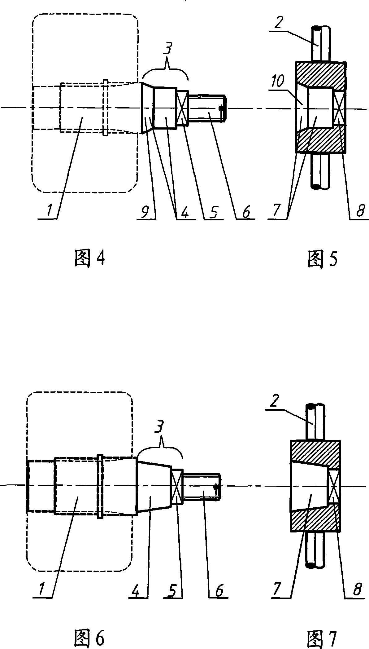
[0024] Embodiment 1 is shown in Figures 1, 2 and 3. The cutter head device of the farmland ditching machine includes cutter head shaft 1 and cutter head 2. The cutter head shaft is divided into two parts: the cutter head assembly section 4 and the cutter head positioning section 5 from the inside to the outside in the section 3 that matches the cutter head shaft hole. , the outermost end is the screw segment 6. The ratio of the length of the cutterhead assembly section to the cutterhead positioning section is 4:1. The cutterhead positioning section is a quadrangular prism; corresponding to the cutterhead assembly section and the cutterhead positioning section of the cutterhead shaft, the cutterhead shaft hole is also divided into two sections, the cutterhead assembly hole 7 and the cutterhead positioning hole 8, and the cutterhead assembly The hole is an inner cylindrical hole, and the positioning hole of the cutter head is an inner quadrangular prism hole. The coupling gap ...


PUM


Abstract

The invention discloses a cutter head device of a farmland ditcher, including a cutter head axis and a cutter head; the cutter head device is characterized in that the section of the cutter head axis which is matched with a cutter head axis hole can be divided into two parts of a cutter head assembling segment and a cutter head positioning segment from inside to outside, the cutter head assembling segment is a cylinder or a truncated cone, and the cutter head positioning segment is a prism; being corresponding to the cutter head assembling segment and the cutter head positioning segment of the cutter head axis, the cutter head axis hole can be divided into a cutter head assembling hole and a cutter head positioning hole, the cutter head assembling hole is a cylindrical inner hole or a truncated cone inner hole, and the cutter head positioning hole is a prism inner hole. The cutter head device overcomes the defects existing in the prior art for a long time that the disassembly of single key and spline cutter heads is troublesome, the cutter head can be inversely installed but is hard to use and likely to be damaged. The cutter head device has simple structure, easy processing as well as convenient, quick and reliable assembly and disassembly.

Description

technical field [0001] The invention belongs to a farmland ditching machine in the field of agricultural machinery, and in particular relates to a cutter head device of a farmland ditching machine. Background technique [0002] Chinese utility model patent "farmland ditching machine" (authorization announcement number: CN2375068Y, patent number: 99228497) discloses a kind of single cantilever type farmland ditching machine, has been widely used now. Because it is a ditching machine that is matched with a walking tractor and is arranged at the front of the tractor head. When ditching, the cutter head of the ditching machine must be lowered into the soil to a certain depth, so the front of the walking tractor should be inclined downward, but if the inclination is too large, it is not conducive to the lubricating oil supply of the horizontal diesel engine and the cooling water will overflow , the user is also inconvenient to operate. In order to reduce the labor intensity of ...

Claims


Application Information

Patent Timeline
Patent Type & Authority Patents(China)
IPC IPC(8): A01B33/14
Inventor 葛玉明葛伟岸
Owner 葛玉明
Why Eureka
Try Eureka