

Fluid filter
A fluid filter and filter technology, applied in the direction of membrane filter, cartridge filter, filtration separation, etc., can solve the problems of protrusion and filter housing wear, foreign matter generation, etc.
- Summary
- Abstract
- Description
- Claims
- Application Information
AI Technical Summary
Problems solved by technology
Method used
Image

Examples
no. 1 example
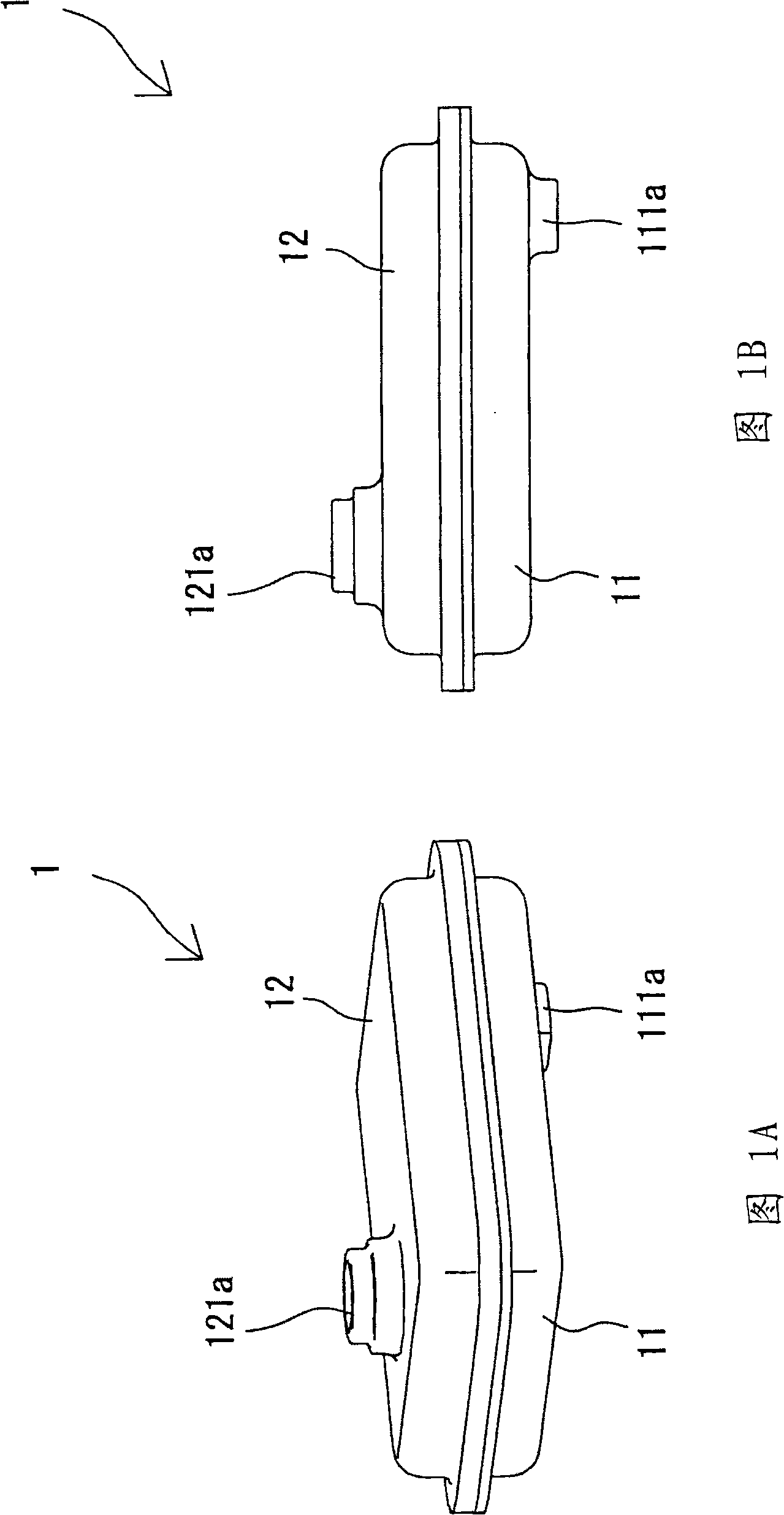
[0051] 1A and 1B, an oil filter 1 includes a housing 11 as a filter housing, a cover 12 as a filter housing connected to the housing 11, and a filter element located between the housing 11 and the cover 12. 13. The oil filter 1 has a longitudinal direction (the direction in which the ribs 133 extend), a transverse direction perpendicular to the longitudinal direction, and a transverse position in the transverse direction.
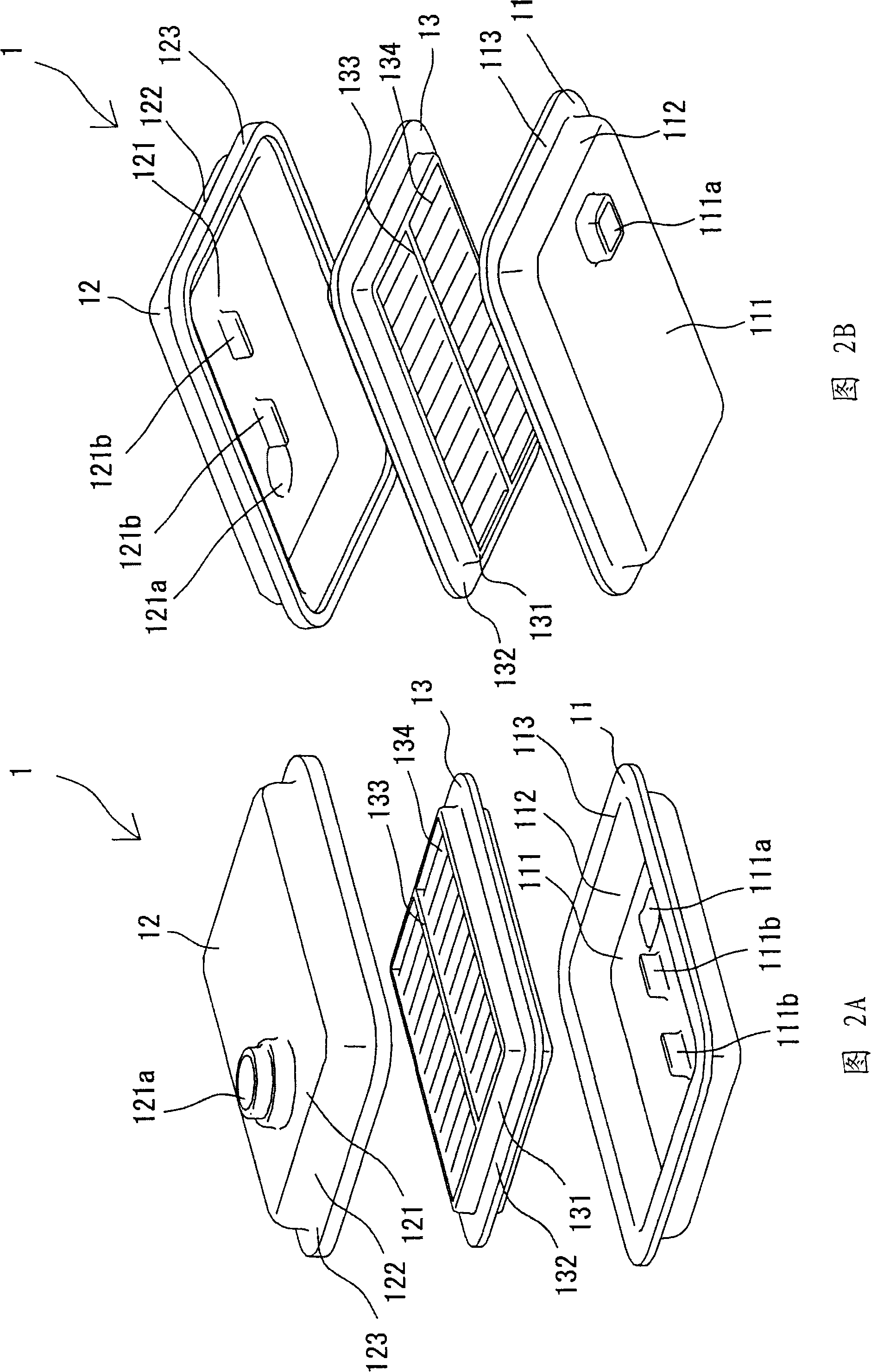
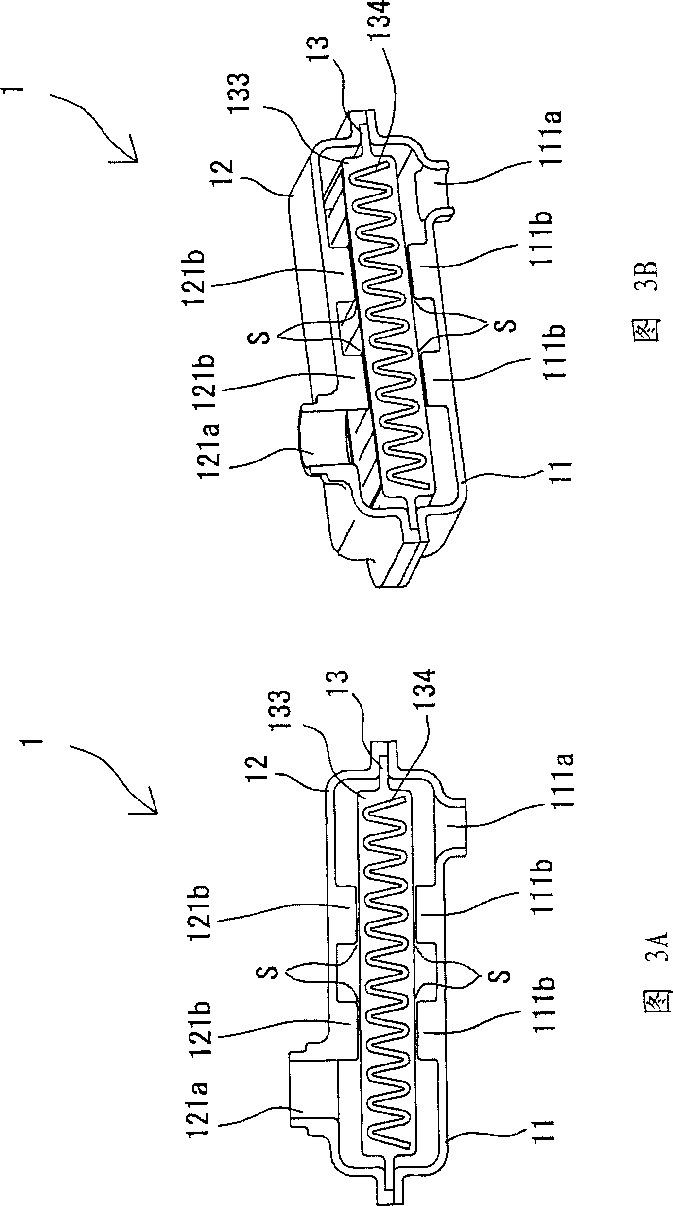
[0052] In FIGS. 2A , 2B, 3A and 3B, the rectangular housing 11 includes a bottom wall 111 , a side wall 112 extending upward from the outer periphery of the bottom wall 111 , and a flange 113 extending outward from the end of the side wall 112 . The bottom wall 111 has an inlet 111a for oil to enter. The bottom wall 111 has support walls 111b as support members, which are longitudinally aligned with each other.
[0053] The cover 12 includes a top wall 121 , a side wall 122 extending downward from the bottom wall 121 , and a flange 123 extending outward f...
no. 2 example
[0063] Hereinafter, similar reference symbols denote similar components, and descriptions thereof are omitted.
[0064] Referring to Figs. 4A, 4B, 5A and 5B, the oil filter 1A will be described.
[0065] The housing 11A includes a support wall 111c as a support member that extends obliquely to a straight line connecting the inlet 111a and the outlet 121a or obliquely to the rib 133 in plan view.
[0066] The cover 12A includes a support wall 121c as a support member extending obliquely to a straight line connecting the inlet 111a and the outlet 121a or obliquely to the rib 133 in plan view. The pair of support walls 121c located in the transverse direction gradually approach each other from the inlet 111a toward the outlet 112a.
[0067] The filter element 13A includes two rows of longitudinally extending ribs 133 . The rib 133 and the support wall 111c coincide with each other with respect to the lateral position. The rib 133 and the support wall 121c coincide with each ot...
no. 3 example
[0074] Referring to Figs. 6A, 6B, 7A and 7B, the oil filter 1B will be described.
[0075] The housing 11B includes, as a supporting member, rod-shaped supporting protrusions 111d that extend upward from the bottom wall 111 and are longitudinally arranged. The cover 12B includes, as a support member, rod-shaped support protrusions 121d extending downward from the top wall 121 and arranged longitudinally.
[0076] The support protrusions 111d, 121d and the rib 133 are arranged on a straight line connecting the inlet 111a and the outlet 121a in plan view. Thereby, the support protrusion 111d and the rib 133 coincide with each other with respect to the lateral position. The rib 133 and the support protrusion 111d are opposed to each other with a space S between them 133, 111d. The support protrusion 121d and the rib 133 coincide with each other with respect to the lateral position. The rib 133 and the support protrusion 121d are opposed to each other with a space S between the...
PUM
 Abstract
Description
Claims
Application Information