Body force transferring structure for sedan

A technology for car body and car, which is applied in the field of car body structure design to achieve the effect of ensuring living space, reducing intrusion and reducing buffering

Inactive Publication Date: 2008-10-08
CHERY AUTOMOBILE CO LTD
View PDF0 Cites 5 Cited by
  • Summary
  • Abstract
  • Description
  • Claims
  • Application Information

AI Technical Summary

Problems solved by technology

However, how can the deformation of other parts of the body be mobilized through the deformation of the front cabin and maintain sufficient strength to protect the occupants? This is actually the problem of setting the force transmission path in the entire body structure design.

Method used


Image

  • Body force transferring structure for sedan
  • Body force transferring structure for sedan
  • Body force transferring structure for sedan

Examples


Embodiment Construction

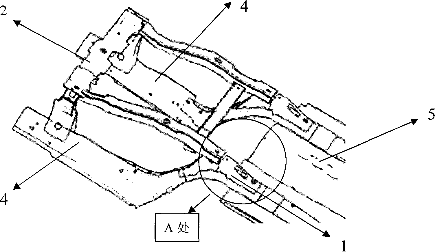
[0015] refer to figure 1 , in a preferred embodiment of the present invention, it can be seen that the vehicle body force transmission structure of the car of the present invention includes the traditional front part design of the vehicle body: sub-frame assembly 2, left and right longitudinal beam assembly 4, front floor assembly 5 ; also includes a force transmission structure 1, the force transmission structure 1 is welded on the welding assembly composed of the sub-frame assembly 2 and the front floor assembly 5, welded symmetrically from left to right, and facing the sub-frame assembly 2 In this way, a large amount of force generated by the collision will continue to be transmitted to the front floor assembly 5 through the force transmission structure 1 .

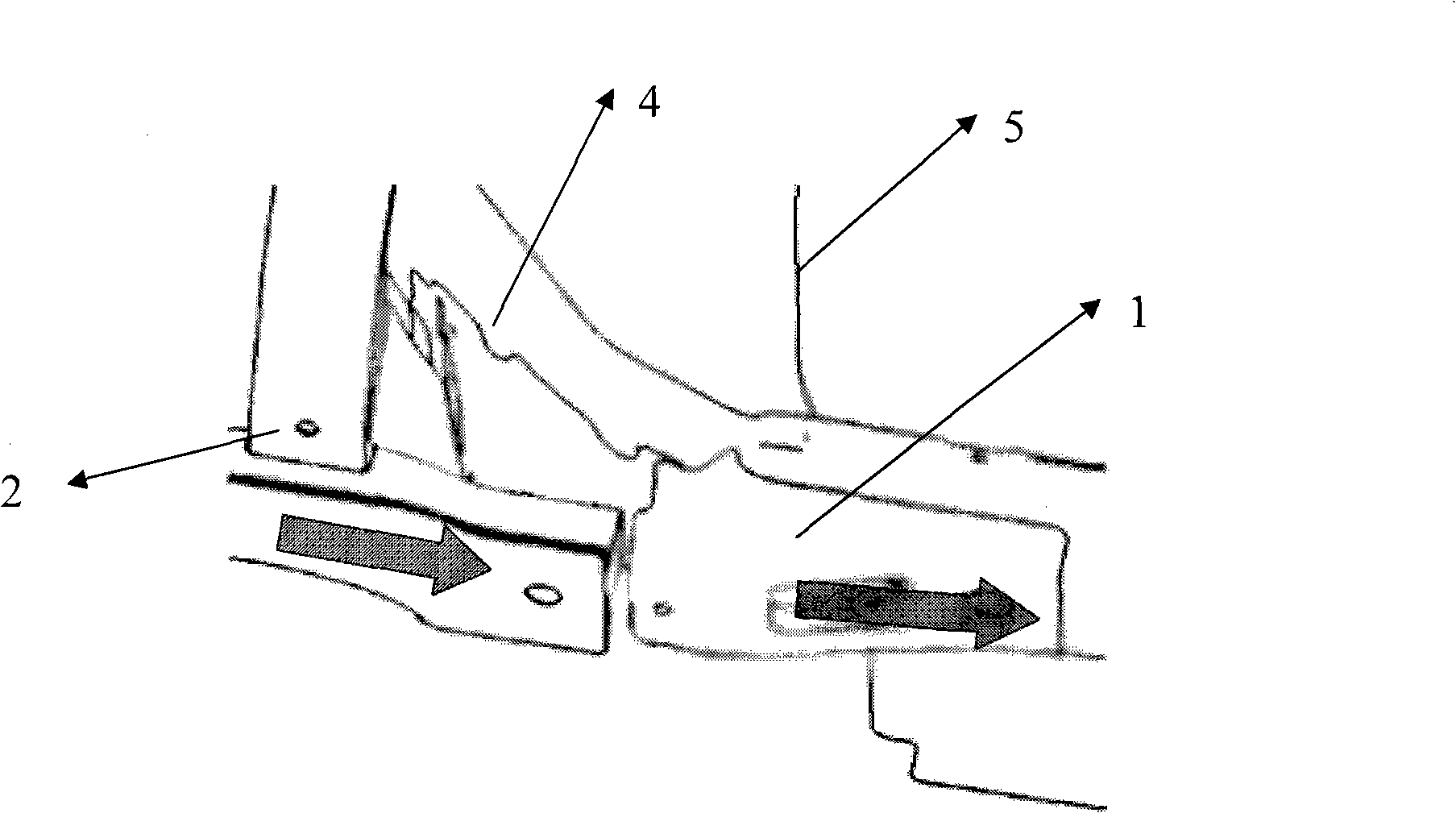
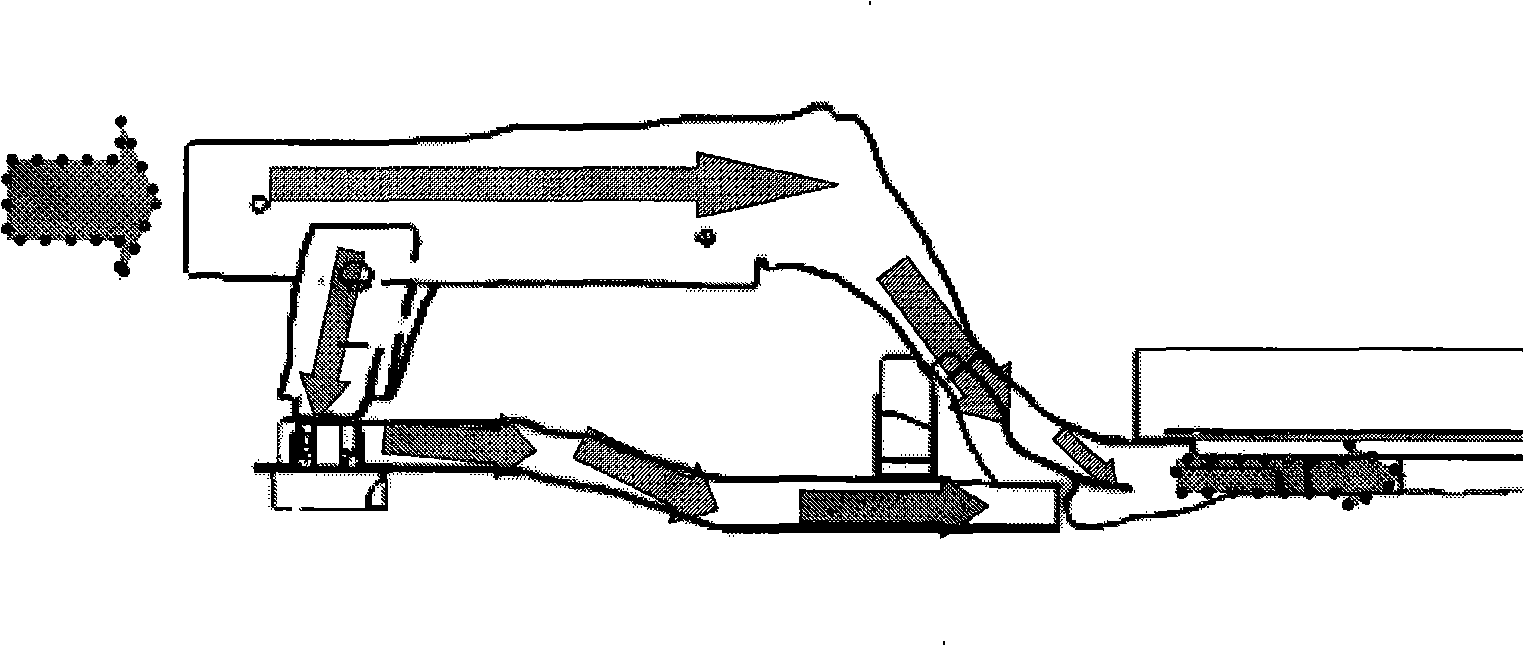
[0016] figure 2 yes figure 1 Partial enlarged view of A. The arrow system shows that the force is transmitted from the sub-frame assembly 2 of the vehicle body to the front floor assembly 5 in the middle of the veh...


PUM


Abstract

The invention provides a vehicle body force-transmission structure for cars, comprising traditional front design of the vehicle body: a sub-frame assembly 2, a left and right longitudinal beam assembly 4 and a front floor assembly 5; the invention also comprises force-transmission structure 1, which is welded onto a welding assembly consisting of the sub-frame assembly 2 and the front floor assembly 5 symmetrically in left and right and is just opposite to the end of the sub-frame assembly 2, so the large amount of force produced by collision can be unceasingly transmitted to the front floor assembly 5 through the force-transmission structure 1, causing the force transmission to reach continuity, and guaranteeing each part of the vehicle body absorbs energy fully, thereby reducing the acceleration, decreasing the cushion, reducing the intrusion amount in the cab and guaranteeing the living space of the passengers.

Description

technical field [0001] The invention belongs to the field of automobiles, and mainly relates to the structural design of car bodies. Background technique [0002] For small-displacement cars, the body structure design must meet the same regulatory requirements as large-displacement cars in a limited space. The front compartment structure (the middle finger sub-frame assembly 2 of the present invention) and the middle rear structure (the front floor assembly 5 of the middle finger of the present invention) are disengaged between the front cabin structure in the traditional structure, and there is no any structural connection. In this way, the force generated in the collision breaks between the sub-frame assembly 2 and the front floor assembly 5 of the vehicle body, and it is easy to cause unpredictable chaotic deformation and collapse of the front structure. Acceleration damages the occupant, and secondly, due to chaotic deformation and collapse, the occupant's living space ...

Claims


Application Information

Patent Timeline
Patent Type & Authority Applications(China)
IPC IPC(8): B62D23/00
Inventor 郭远方彭桂玲朱志军
Owner CHERY AUTOMOBILE CO LTD
Why Eureka
Try Eureka