Electric apparatus remote-control device and method based on passive standby

A remote control device and passive standby technology, which is applied in the direction of instruments, electrical signal transmission systems, signal transmission systems, etc., can solve problems such as shortened service life, waste of energy, and potential safety hazards, so as to prolong service life, save electric energy, and improve The effect of the safety index

Active Publication Date: 2008-10-08
周爱华
View PDF0 Cites 15 Cited by
  • Summary
  • Abstract
  • Description
  • Claims
  • Application Information

AI Technical Summary

Problems solved by technology

[0008] In a word, adopting the remote control device in the prior art will inevitably bring the following defects: the standby power consumption of the electrical equipment is increased, which wastes energy; Hidden danger

Method used


Image

  • Electric apparatus remote-control device and method based on passive standby
  • Electric apparatus remote-control device and method based on passive standby
  • Electric apparatus remote-control device and method based on passive standby

Examples


Embodiment 1

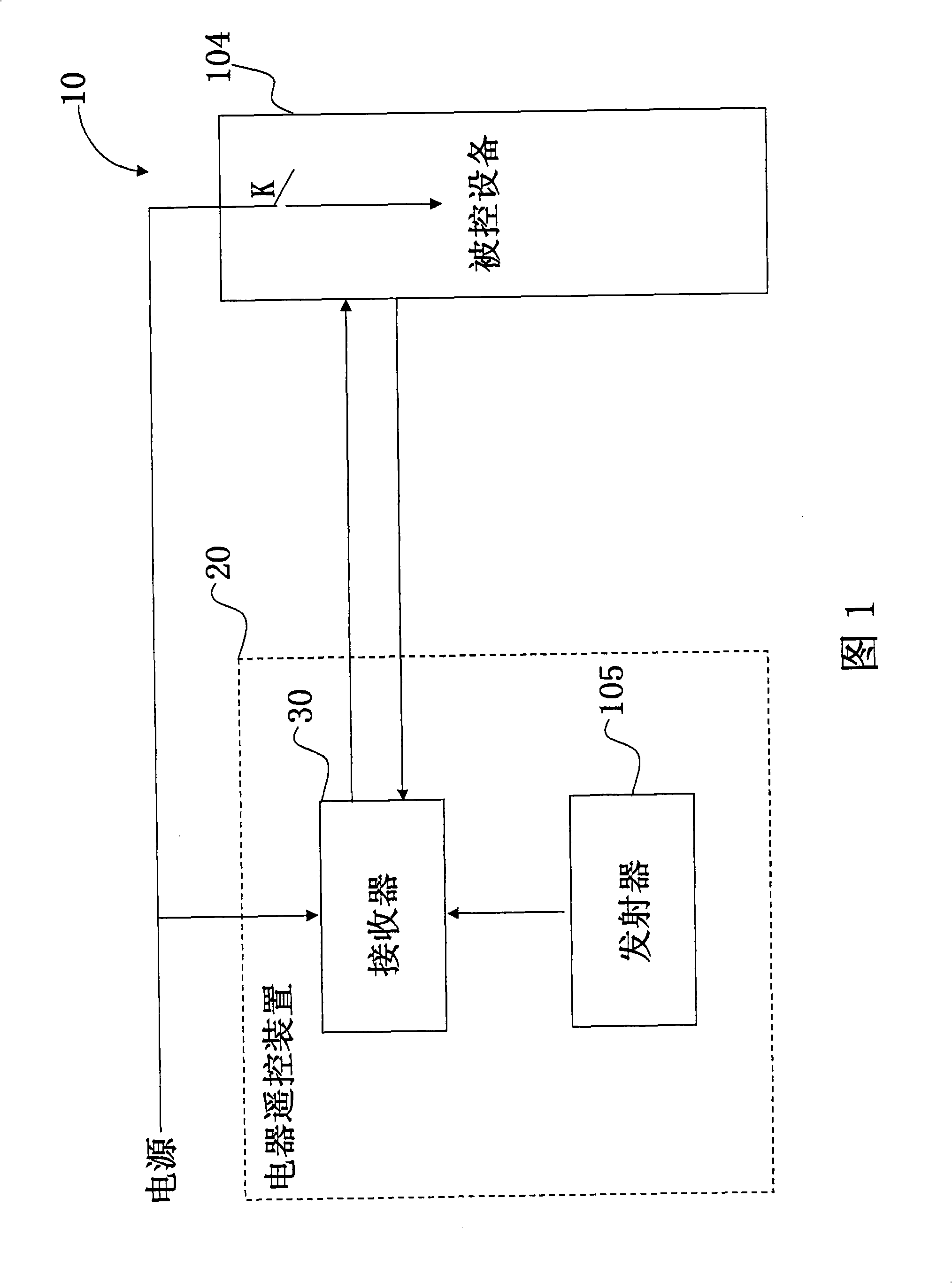
[0022] The present invention provides a remote control device for electrical appliances based on passive standby. As shown in FIG. 1 , the remote control device 20 for electrical appliances includes a transmitter 105 and a receiver 30; ; Wherein, the remote control appliance 10 can be a variety of remote control appliances, such as televisions, computers, air conditioners, etc., the present invention is not limited thereto.

[0023] The transmitter 105 is composed of one or more transmitting circuits, wherein the transmitting power of each transmitting circuit is different.

[0024] The transmitter 105 is used to transmit a signal carrying a certain energy to the receiver 30 , and the signal carrying a certain energy transmitted by the transmitter 105 includes various forms of signals including sound waves, light waves or electromagnetic waves.

[0025] The receiver 30 receives the signal carrying a certain amount of energy transmitted by the above-mentioned transmitter 105, c...

Embodiment 2

[0052] The present invention also provides a remote control method for electrical appliances. Please refer to FIGS. 1 , 2 , 11 , 12 and 13 for a detailed description of how the remote control device 20 for electrical appliances in Embodiment 1 realizes the remote control method for electrical appliances of the present invention.

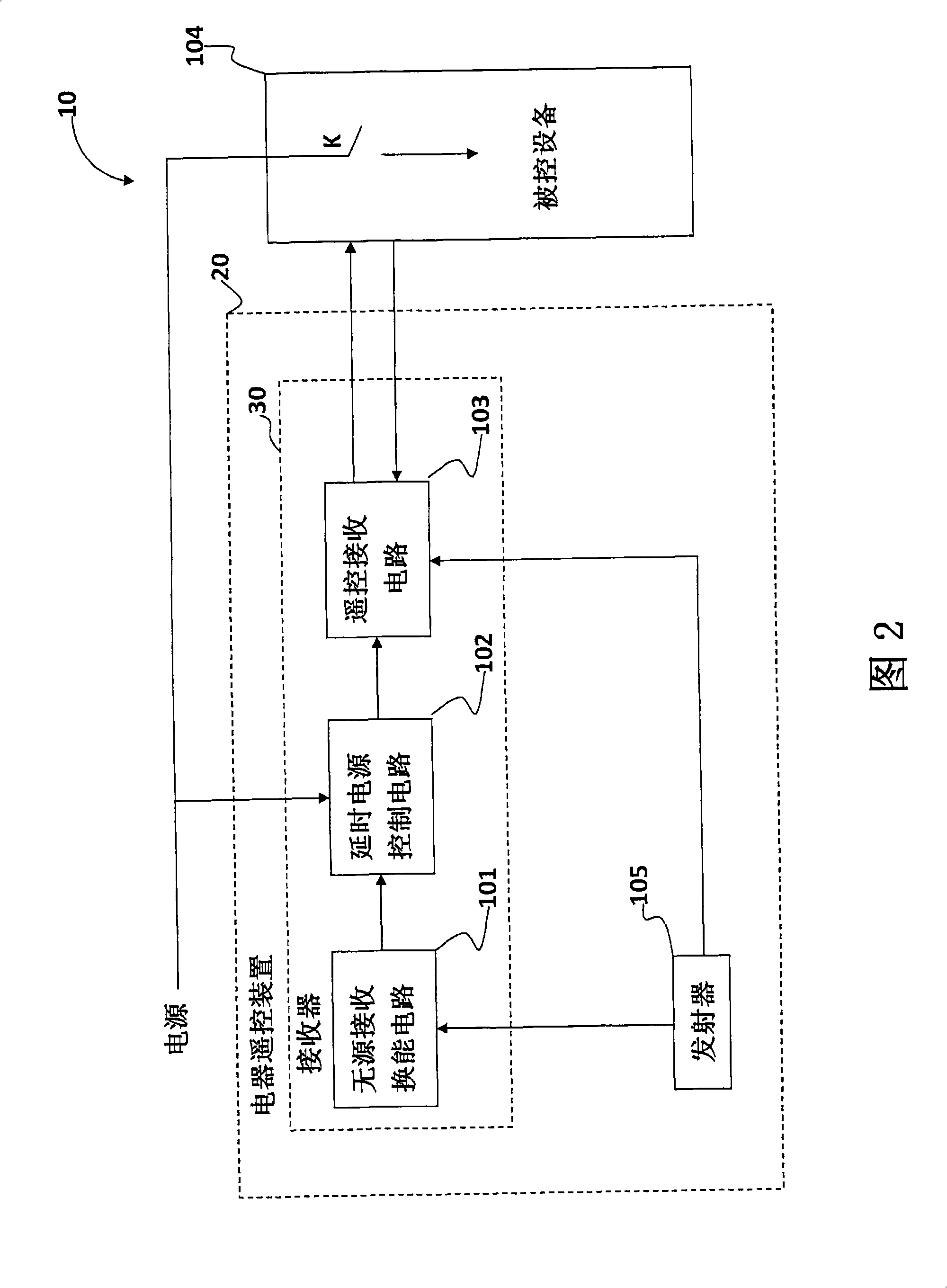
[0053] See Figure 11 The electric appliance remote control method includes the following steps: connecting the Z1 and Z2 contacts of the passive receiving transducer circuit 101 with the Z1 and Z2 contacts of the delay power control circuit 102, and connecting the AC220V end of the delay power control circuit 102 to the market Electrically connected, the power output end of the delay power control circuit 102 is connected to the power input end of the remote control receiving circuit 103, and the power input end of the remote control receiving circuit 103 is connected to the corresponding power supply of the controlled device 104 of the remote contro...


PUM


Abstract

The invention provides an electrical appliance remote control unit and a method based on the passive standby, wherein the electrical appliance remote control unit and the controlled device are constructed as the remotely controlled appliance. The electrical appliance remote control unit includes a receiver and an emitter; the emitter is used for transmitting the signals burdening certain energy to the receiver; the receiver receives the signals and the signals are converted to the electrical signal and trigger the receiver, and the power supply is used to supply power to the receiver in a certain time, thereby making the remotely controlled appliance in the active standby state in a certain time. When the remotely controlled appliance is in the active standby state, the emitter transmits the corresponding operation signals to the receiver; after the receiver receives the operation signals, the controlled device is started to work; and when the controlled device works normally, the device supplies power to the receiver. By the invention, other electrical appliances do not consume any energy when the whole device does not trigger by the outside energy and the remotely controlled appliance is in the working state.

Description

technical field [0001] The invention relates to the field of electrical remote control, in particular to an electrical remote control device and method based on passive standby. Background technique [0002] At present, the use of electrical equipment is increasingly frequent and extensive, and when users use electrical equipment, such as TVs and electric lights in household appliances, they all need to manually turn on and off the power switch at the place where the switch is set, which is extremely inconvenient to use. . [0003] With the development of science and technology, for the convenience of use, various standby functions such as remote control switch, network wake-up, and timer switch are set on the above-mentioned electrical equipment, and the electrical equipment can be operated and used only by pressing the remote control. [0004] In the prior art, the remote control devices all adopt the active receiving mode, and whether the signal transmitted by the remote...

Claims


Application Information

Patent Timeline
Patent Type & Authority Applications(China)
IPC IPC(8): G08C17/00G08C19/00
Inventor 周爱华
Owner 周爱华
Why Eureka
Try Eureka