Apparatus and method for displaying battery dump energy

A technology of remaining battery power and remaining power, applied in measuring devices, current supply devices, secondary batteries, etc., can solve the problem that users cannot fully and truly understand the remaining battery power, and achieve the effect of increasing initiative and convenient use.

Inactive Publication Date: 2008-10-08
LG ELECTRONICS (CHINA) R&D CENT CO LTD
View PDF0 Cites 32 Cited by
  • Summary
  • Abstract
  • Description
  • Claims
  • Application Information

AI Technical Summary

Problems solved by technology

[0008] The invention provides a device and method for displaying the remaining battery power, which can simultaneously display the remaining battery power and the current voltage for user reference, and solves the problem that the existing technology only displays the remaining power based on the voltage measurement or current integration results, and cannot make the user fully Realistically understand the pitfalls of remaining battery power

Method used


Image

  • Apparatus and method for displaying battery dump energy
  • Apparatus and method for displaying battery dump energy
  • Apparatus and method for displaying battery dump energy

Examples


Embodiment 1

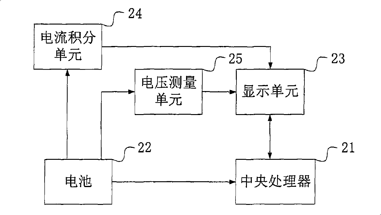
[0035] figure 2 It is a functional block diagram of Embodiment 1, which shows a simplified schematic diagram of a battery-driven device, which includes components related to this embodiment. The device is any device that requires battery-driven and can display battery power, such as mobile terminals, multimedia players and more. As shown in the figure, the device includes (but not limited to) a central processing unit 21 , a battery 22 , a display unit 23 , a current integration unit 24 and a voltage measurement unit 25 .

[0036] The central processing unit 21 is connected to a battery 22 and a display unit 23 . The current integration unit 24 is connected to the battery 22 and the display unit 23 , and is used to obtain the consumed power of the battery through current integration, generate the remaining power of the battery, and transmit the remaining power value to the display unit 23 . The voltage measuring unit 25 is connected to the battery 22 and the display unit 23...

Embodiment approach

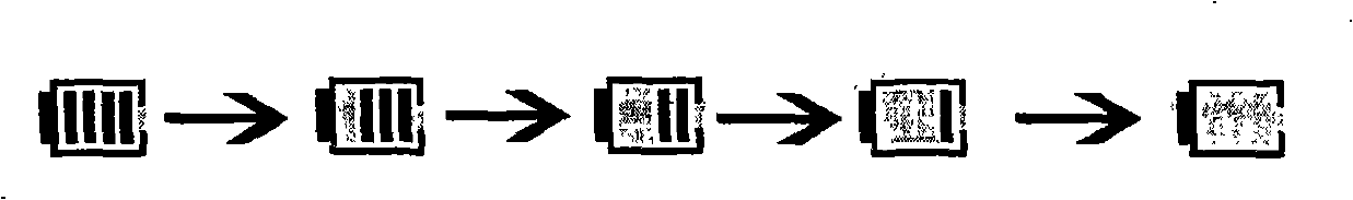
[0056] In this embodiment, two sets of status bars can be used to represent the current voltage and the remaining battery power respectively. The number of the first group of status bars represents the current voltage, and the number of the second group of status bars represents the remaining power. Figure 7a The upper and lower rows of battery icons reflect the current voltage and remaining power. The upper row of icons represents the current voltage, and the lower row of icons represents the remaining power. The two icons aligned up and down represent a combination. Figure 7a The CCP shows five possible combinations (not limited to these five combinations), each combination corresponds to the current voltage and remaining power information of the battery at the time of measurement, and these combinations reflect the current voltage and remaining battery power at different times Information.

[0057] In this embodiment, two status bars can also be used to represent the curr...

Embodiment 3

[0061] This embodiment considers that when some users need to know accurate measurement values, the battery-driven device can display the measurement values ​​of the current voltage and the remaining power, instead of only providing a rough grade to the user.

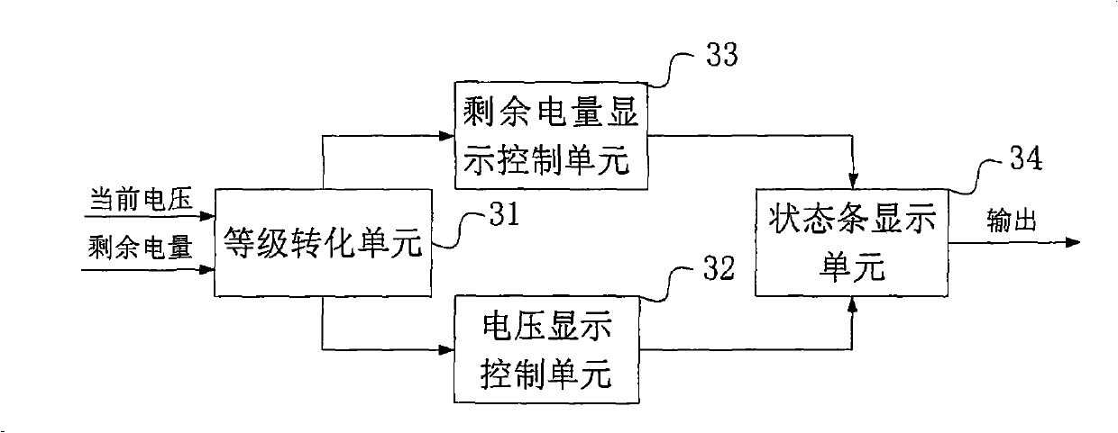
[0062] The overall functional block diagram of this embodiment continues to use figure 2 , the detailed structural diagram of the display unit 23 of this embodiment is Figure 8 ,with image 3 the difference is, Figure 8 It also includes a measured value display unit 81 for displaying the actual measured values ​​of the current voltage and the remaining power. as in image 3 or Figure 4 The voltage direction of the status bar (the direction in which the number of status bars decreases) displays the actual measured value of the current voltage; the height direction of the status bar (the direction perpendicular to the voltage direction) displays the value of the remaining power.

[0063] In this embodiment, two-d...


PUM


Abstract

The invention provides a device and method for displaying residual electric quantity of a battery, the device includes: a current integration unit for acquiring consumed electric quantity of the battery through current integration and creates residual quantity of the battery; a voltage measuring unit for measuring battery voltage to create current voltage of the battery; a display unit for displaying information of residual electric quantity and current voltage of the battery. The invention displays residual electric quantity and current voltage on a display synchronously, which can provides more comprehensive and accurate battery state information to users and increases initiative of users when using the battery power-supply equipment, utilizations of users are facilitated.

Description

technical field [0001] The present invention relates to the technical field of power management, in particular to a device and method for displaying remaining battery power. Background technique [0002] Power management technology is very important for all kinds of devices that need battery power. Insufficient power will cause some devices to be powered off and shut down. Therefore, users need to obtain real-time information on battery usage status, especially the remaining power information of the battery, and based on this information Control the normal operation of the equipment. [0003] In the prior art, there is generally a schematic diagram showing the remaining power of the battery on the display screen, which contains a plurality of status bars. When the power is full, each status bar is full. When the power is slowly consumed, The number of status bars will decrease in turn until all status bars are not displayed when the battery is exhausted. figure 1 It shows ...

Claims


Application Information

Patent Timeline
Patent Type & Authority Applications(China)
IPC IPC(8): H04M3/487H04M1/73H01M10/48G01R31/36
CPCY02E60/10
Inventor 阮建辉
Owner LG ELECTRONICS (CHINA) R&D CENT CO LTD
Why Eureka
Try Eureka