

Wireless communication base station device and pilot transmitting method
A technology of wireless communication and wireless communication system, applied in the field of wireless communication base station device and pilot frequency transmission, can solve the problems of frequency selective fading, deterioration of transmission characteristics, etc., and achieve the effect of improving interpolation accuracy
- Summary
- Abstract
- Description
- Claims
- Application Information
AI Technical Summary
Problems solved by technology
Method used
Image

Examples
Embodiment approach 1
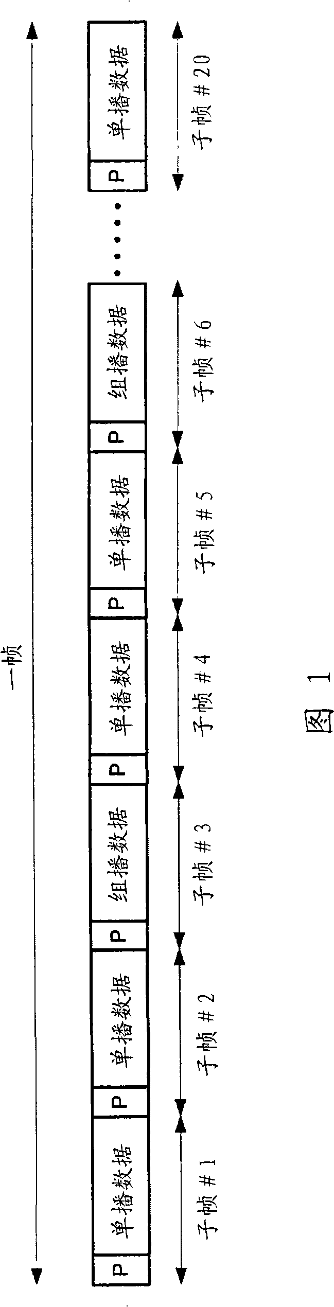
[0044] The base station according to this embodiment is a base station used in a wireless communication system in which subframes for multiple base stations to transmit mutually different data and subframes for multiple base stations to transmit mutually identical data The subframes are time multiplexed. The base station of this embodiment is particularly suitable for the following wireless communication system, that is, as shown in FIG. Hereinafter, it is referred to as a system in which multicast subframes) are time-multiplexed. Therefore, in the following description, a unicast subframe is used as a subframe for multiple base stations to transmit mutually different data, and a multicast subframe is used as a subframe for multiple base stations to transmit mutually identical data To illustrate with an example. In addition, the frame structure in this embodiment is the same as that in FIG. 1 .
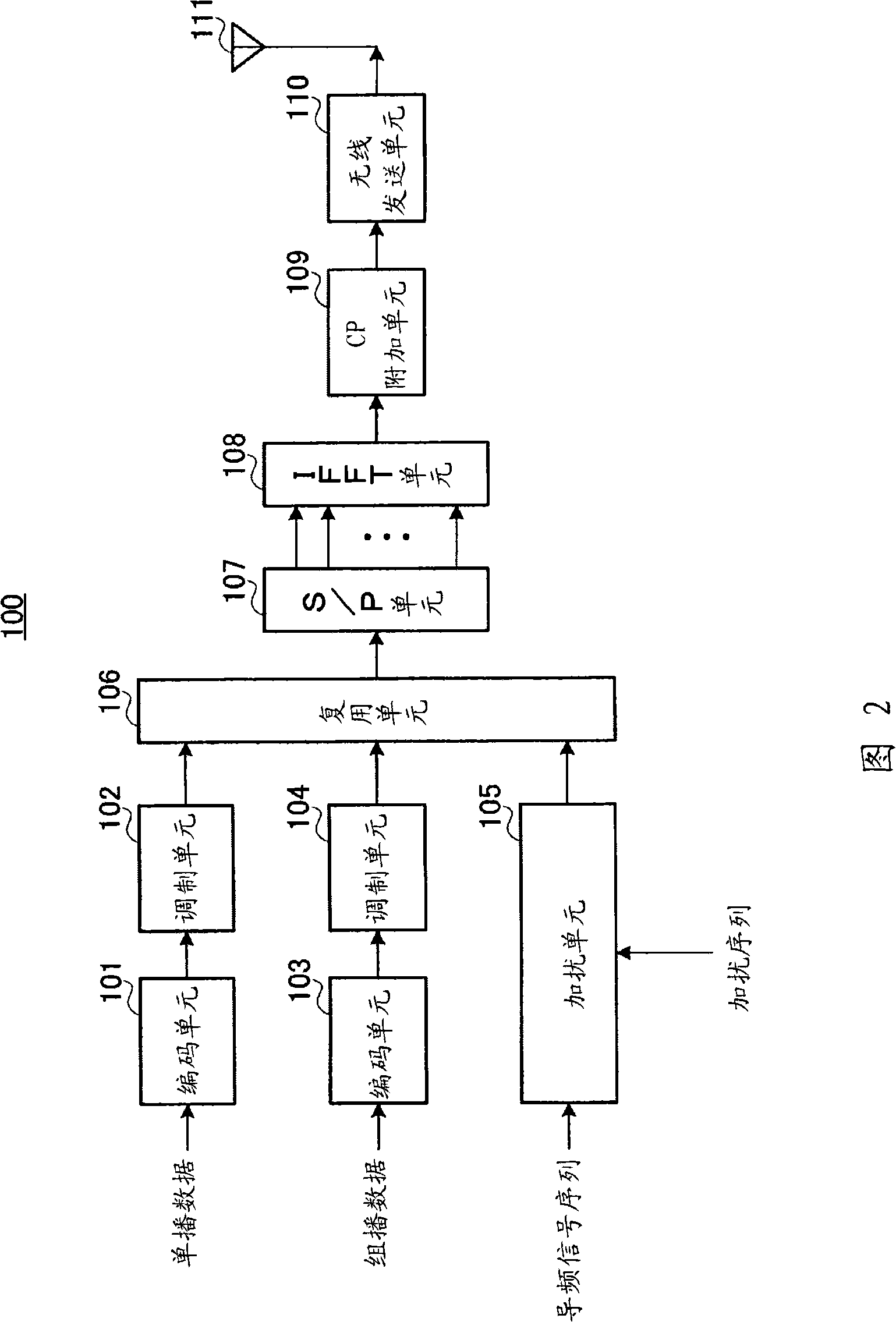
[0045] FIG. 2 shows the configuration of the base station 100 according to the...
Embodiment approach 2
[0097] In Embodiment 1, the channel estimation value g calculated when performing channel estimation on multicast data i , as mentioned above is the channel estimate h in cell A i and the channel estimate l in cell B i The channel estimation value is mixed, so the channel estimation value cannot be used for channel estimation of unicast data.
[0098] Therefore, in the present embodiment, among the eigensequences and common sequences included in the scrambling sequence, a phase rotation specific to each base station that is different for each cell is given to the common sequence.
[0099] FIG. 16 shows the configuration of base station 500 according to this embodiment. Base station 500 is configured by including phase rotation units 501 and 502 in addition to the configuration shown in Embodiment 1 ( FIG. 2 ). In addition, in FIG. 16 , the same components as those in FIG. 2 are given the same reference numerals, and description thereof will be omitted.
[0100] In base sta...
Embodiment approach 3
[0109] In this embodiment, a case will be described in which mutually different multicast data are transmitted for each of a plurality of cell groups constituted by a plurality of cells. In this embodiment, for example, as shown in FIG. 18 , it is assumed that when cell group 1 is constituted by cells A to G and cell group 2 is constituted by cells H to N, multicast data 1 is transmitted in cells A to G of cell group 1. On the other hand, in the cells H to N of the cell group 2, the multicast data 2 different from the multicast data 1 is transmitted.
[0110] At this time, if the pilots for the multicast subframe are configured at the same position in all the cells, in the cells located at the boundary of the cell group (in FIG. 18 , cells A, B, M, and N), it is expected that the group channel estimation accuracy of broadcast data deteriorates. For example, it is expected that in the cells A and B of the cell group 1, the channel estimation accuracy of the multicast data 1 de...
PUM
 Abstract
Description
Claims
Application Information