
Multi-cutter complex cyclone milling processing method and special topping mechanism thereof

A processing method and cutting device technology, applied in the direction of driving devices, metal processing equipment, metal processing machinery parts, etc., can solve the problem of high power output power, achieve power output power reduction, improve cutting resistance, improve efficacy and surface The effect of machining accuracy

Inactive Publication Date: 2008-10-15
张永康 +2
View PDF0 Cites 12 Cited by
  • Summary
  • Abstract
  • Description
  • Claims
  • Application Information

AI Technical Summary

Problems solved by technology

Although this processing method can overcome many disadvantages of turning, it is still limited by the cutting amount of the tool once for heavy cutting, and it needs to be completed many times, and the power output power required is also large.

Method used


Image

  • Multi-cutter complex cyclone milling processing method and special topping mechanism thereof
  • Multi-cutter complex cyclone milling processing method and special topping mechanism thereof
  • Multi-cutter complex cyclone milling processing method and special topping mechanism thereof

Examples


Embodiment

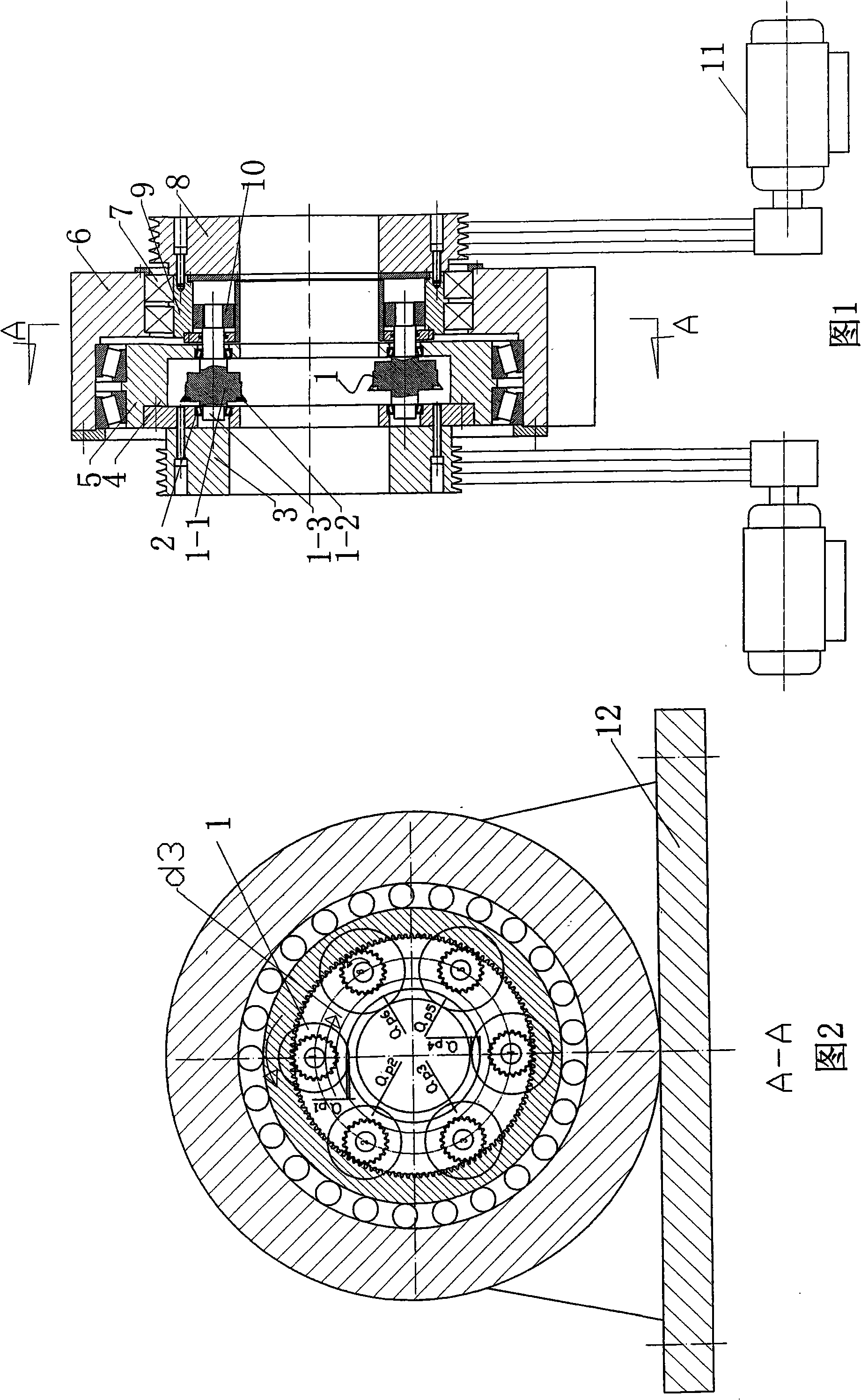
[0041] Example: Process the round steel of Φ270×6000 into a workpiece of d=Φ230×6000

[0042] 1. Select the number of planetary gears

[0043] N W = dπ 170 + π = 230 × 3.14 170 + 3.14 = 7

[0044] Selected planetary gear N W = 6

[0045] 2. Determine the speed n of the planetary gear 2

[0046] 1,

[0047] 2. The cutting depth of each cutter body is divided into six cutter bodies a p = 20 6 = 3.3 mm

[0048] 3. Select the ring gear and the planetary gear modulus m=4

[0049] 4. Select the number of teeth of the inner ring gear z 1 =120

[0050] 5. Select the number of planetary gear teeth z 2 =21

[0051] 6. Th...


PUM


Abstract

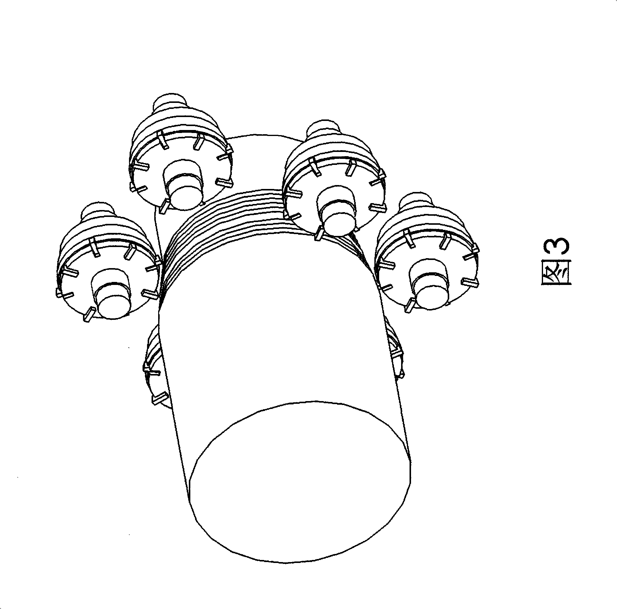
The invention relates to a multi-cutter combined whirlwind milling method and a dedicated cutting device thereof. The multi-cutter combined whirlwind milling method is adopted for processing shaft-type products. The dedicated cutting device is characterized in that the shaft of the cutter body is supported on a revolving body through a bearing; at least a cutter body is distributed and connected on the concentric circumference of the revolving body; each cutter body is connected with a transmission mechanism for enabling the cutter body to rotate; the revolving body is connected with a fixed sleeve support through a bearing and driven by a motor and a transmission mechanism. The method has the advantages that a plurality of cutter bodies revolving along the revolving body as well as rotating automatically are fixed on the concentric circumference of the revolving body, and each cutter performs high-speed cutting on different processing diameters, thus improving the cutting resistance. By the method, the purpose of saving energy, improving effect and surface machining precision can be fulfilled. The production efficiency of the cutting device is improved a plurality of times compared to an ordinary whirlwind milling machine, and dozens of times compared to turning efficiency. Under the same cutting condition, the power output is greatly reduced.

Description

technical field [0001] The invention belongs to mechanical processing methods, and in particular relates to a multi-cutter compound cyclone milling processing method and a special cutting device for cutting the outer diameters of shaft products such as slender shafts and mandrels and other parts. Background technique [0002] Generally, when the ratio of length to diameter is greater than 7, it is called a slender shaft, and the shaft with L / d≥25 is called an ultra-slender shaft. The slender shaft is less rigid. At present, the machining industry mainly adopts turning or centerless turning for the rough machining and semi-finishing of the outer diameter of shaft products such as slender shafts and mandrels of metal and non-metal materials. Since the tool is always cutting continuously during turning, a large amount of heat is generated during the cutting process, which increases the cutting resistance. Not only does the machining surface become rough, the efficiency is low...

Claims


Application Information

Patent Timeline
Patent Type & Authority Applications(China)
IPC IPC(8): B23C3/04B23C5/00B23Q5/02
Inventor 张永康闫东华王荣生
Owner 张永康
Learn More