Blower for vehicles

A technology for blowers and vehicles, which is applied to vehicle parts, heating/cooling equipment, air handling equipment, etc., and can solve problems such as deformation of the shell 50

Active Publication Date: 2008-10-15
HANON SYST
View PDF1 Cites 6 Cited by
  • Summary
  • Abstract
  • Description
  • Claims
  • Application Information

AI Technical Summary

Problems solved by technology

[0016] In addition, since the casing 50 is separated by a predetermined interval by the bypass passage 51 outside the scroll 30, the casing 50 is deformed.

Method used


Image

  • Blower for vehicles
  • Blower for vehicles
  • Blower for vehicles

Examples


Embodiment Construction

[0033] Preferred embodiments of the present invention will now be described in more detail with reference to the accompanying drawings.

[0034] In the present invention, descriptions of the same configurations and actions as those of the related art will be omitted.

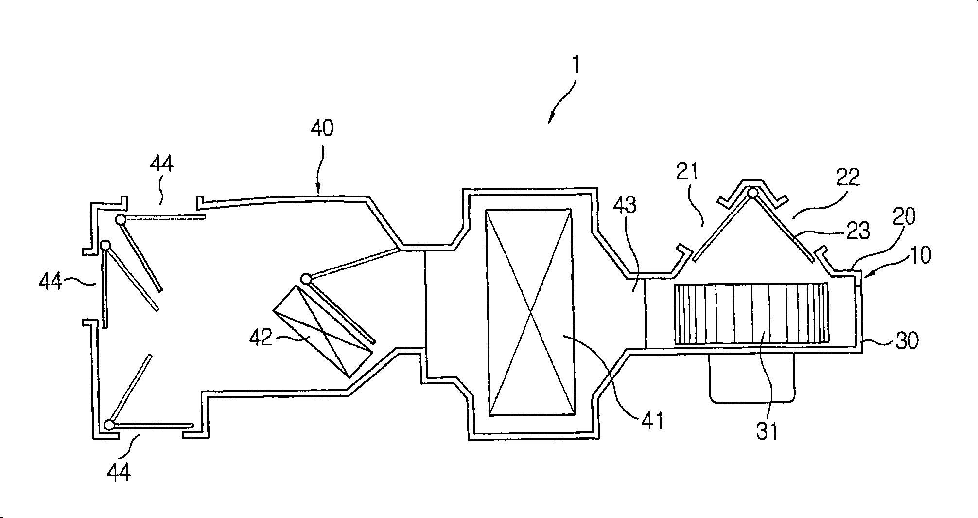
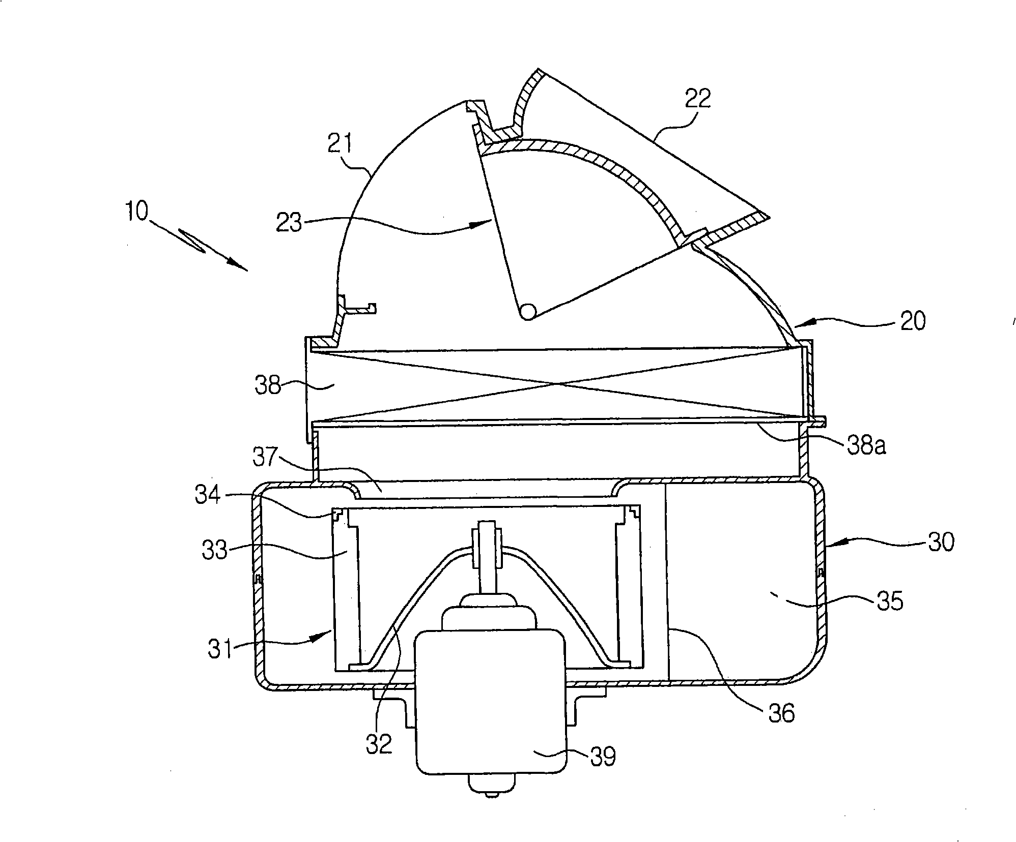
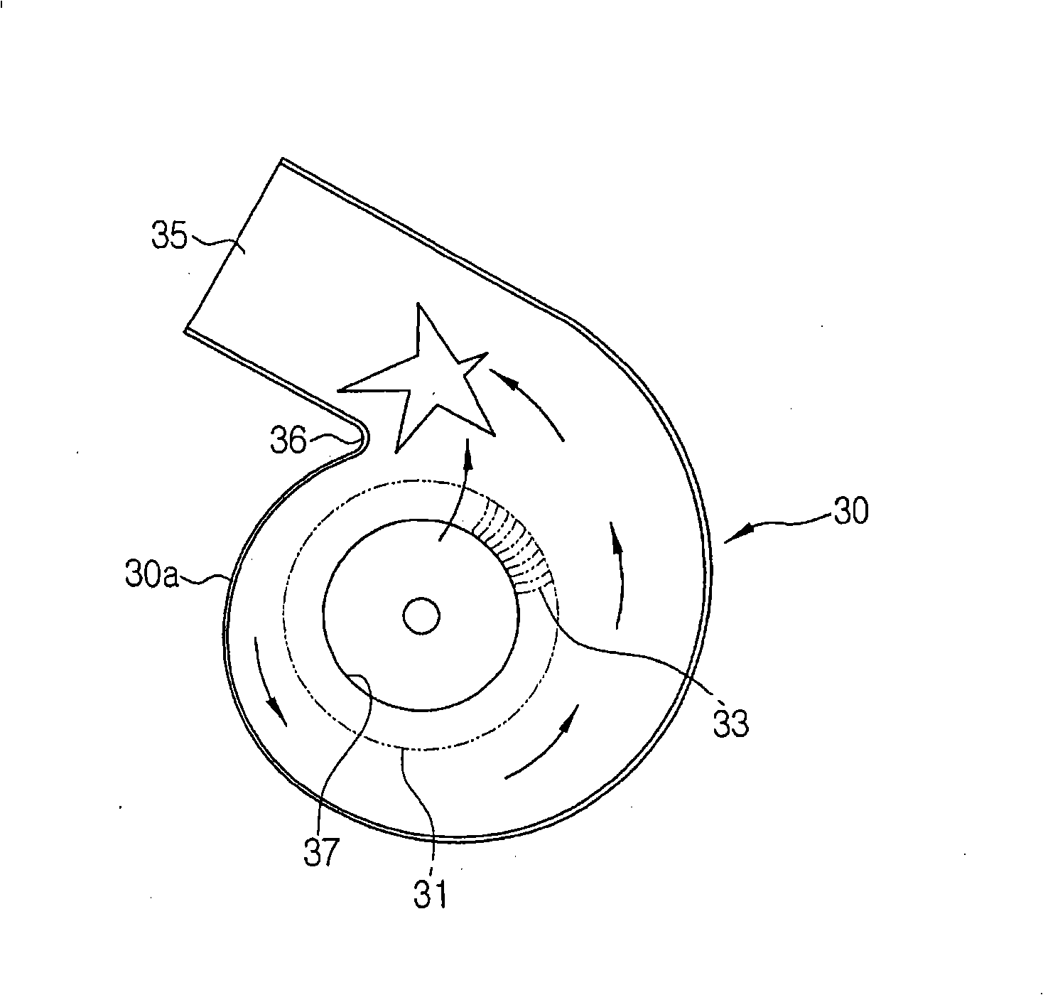
[0035] Figure 5 is an exploded perspective view of a blower for a vehicle according to a preferred embodiment of the present invention, Figure 6 is a plan view showing a state in which an air intake duct is omitted for a blower for a vehicle according to the present invention, Figure 7 is along Figure 5 A sectional view taken along the line A-A, Figure 8 is along Figure 5 A sectional view taken along the line B-B, Figure 9 is a view showing various embodiments of the guide wall of the blower according to the present invention.

[0036] As shown in the figure, the blower 100 according to the present invention includes a volute 120 , a bidirectional suction type blower fan 150 , a casing 130 and an in...


PUM


Abstract

The present invention relates to a blower for vehicles, which includes guide walls formed on a bypass passageway formed between a scroll case and an outer case to send the indoor air and the outdoor air to a lower suction opening of the scroll case, thereby reducing suction noise by guiding a uniform flow of air introduced into the lower suction opening, preventing deformation of the outer case, and preventing a droop of the air filter by supporting a lower portion of an air filter when an intake duct injection-molded in a vertically parted mold is applied thereto.

Description

technical field [0001] The present invention relates to a vehicular blower, and more particularly to such a vehicular blower including a guide wall formed on a bypass passage formed between a volute and a case to deliver indoor air and outdoor air to the volute. The lower suction opening of the shell, thereby reducing suction noise by guiding the uniform air flow introduced into the lower suction opening, preventing deformation of the shell, and when applying the intake duct injection molded in the vertical parting mold, The air filter is prevented from sagging by supporting the lower portion of the air filter. Background technique [0002] In general, a vehicle air conditioner 1 is a device adapted to allow indoor air and outdoor air of a vehicle to be introduced thereinto, to heat or cool the introduced air, and to deliver the heated or cooled air to the interior of the vehicle so as to warm the interior of the vehicle. Heating or cooling. Such as figure 1 As shown, the...

Claims


Application Information

Patent Timeline
Patent Type & Authority Applications(China)
IPC IPC(8): B60H1/24
CPCB60H1/00471B60H2001/00085B60H2001/00092B60H2001/00135B60H1/00564B60H3/06B60H2001/00078B60H2001/006B60H2003/065
Inventor 姜福善金容湘李镕兴朴润哲
Owner HANON SYST
Why Eureka
Try Eureka