Quick release device for rolling screen door

A rolling door and quick-release technology, applied in the field of rolling doors, can solve the problems of easy aging of batteries, strong resistance of users, high system cost, etc., and achieve the effect of simple reset and easy promotion and application

Inactive Publication Date: 2008-10-15
石峥嵘
View PDF0 Cites 6 Cited by
  • Summary
  • Abstract
  • Description
  • Claims
  • Application Information

AI Technical Summary

Problems solved by technology

[0003] 1. Each controller needs to be equipped with a battery, an inverter and an automatic switching circuit. The system cost is high and the user cannot accept it.
[0004] 2. The battery is easy to age, unable to meet the needs of long-term work, and often needs to be replaced
[0005] 3. High failure rate, difficult operation and maintenance
[0006] 4. The emergency guarantee time is not long. Even a new backup power supply can only guarantee power failure for two to three hours. After a period of use, it can only guarantee more than ten minutes, which cannot effectively prevent disasters.
[0007] Based on the above situation, the cost of the fire shutter controller with backup power is relatively high, the practicability is poor, there are many disadvantages, and the user resistance is strong
At present, the fire shutter controller without backup power supply is generally used. This kind of controller cannot link the fire shutter in the state of power failure, and cannot actually effectively protect the fire in the event of a fire.

Method used


Image

  • Quick release device for rolling screen door
  • Quick release device for rolling screen door
  • Quick release device for rolling screen door

Examples


Embodiment 1

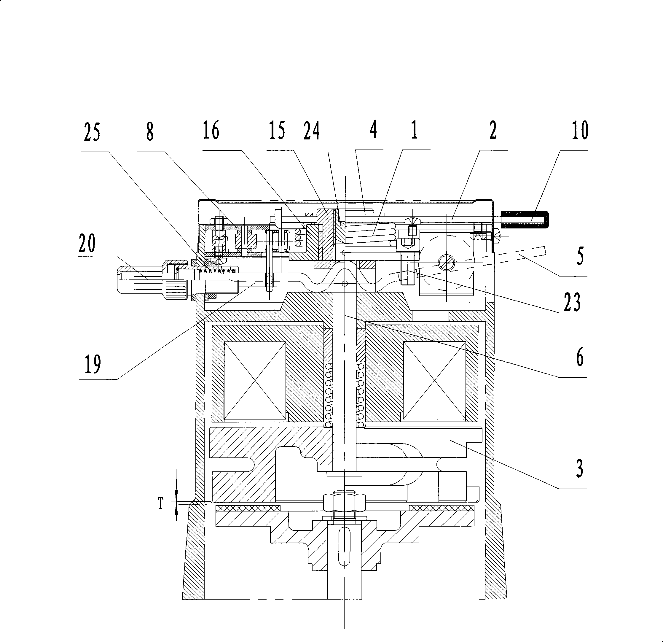
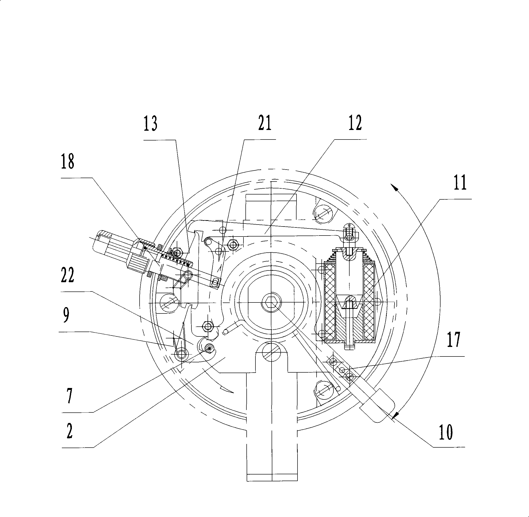
[0043] Example 1: see figure 1 , figure 2 and image 3 As shown, a quick-release device for rolling shutters of the present invention includes a drive plate 2, a mounting plate 8, a lifting mechanism and an electric control starting mechanism, and the lifting mechanism includes a rotating rod 15 and a positioning sleeve 16 that remains fixed. In a specific embodiment, the positioning sleeve 16 can be fixed on the mounting plate 8, the casing or other positions. One end of the rotating rod 15 is fixed on the top of the brake rod 6, and the other end is connected with the driving plate 2. The rotating rod 15 and the positioning sleeve 16 are threadedly connected, and the driving plate 2 drives the rotating rod 15 to rotate under the drive of the electric control starting mechanism. And utilize the screw thread lead angle between the positioning sleeve 16 to drive the brake lever 6 to move up and down. The driving plate 2 is connected with a torsion spring 1 fixed on the moun...

Embodiment 2

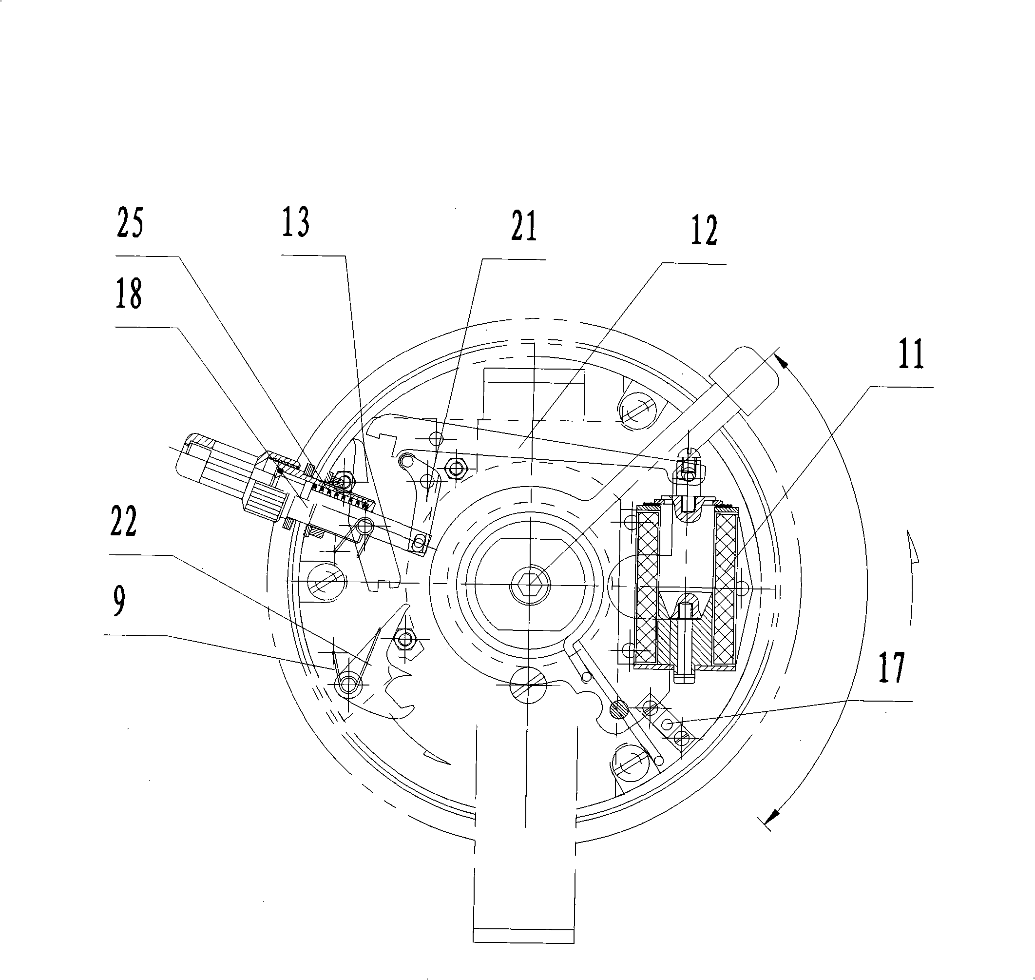
[0046] Example 2: see Figure 4 , Figure 5 and Figure 6 As shown, the structure is basically the same as that of Embodiment 1, and the difference is that the electronically controlled driving mechanism adopts an electric explosive head 14 connected to the control center, and the electric explosive head 14 is connected with a temperature-sensitive starting mechanism, and the temperature-sensitive starting mechanism includes a fixed The temperature sensing device 18 on the motor housing, the temperature sensing starting rod 19 and the stage clip 25, the stage clip 25 is enclosed within on the temperature sensing starting rod 19, the electric explosive head 14 is fixed on the driving plate 2, and the driving plate 2 passes through the electric Explosive head 14 is buckled on the temperature-sensitive starting rod 19, and when temperature-sensitive starting rod 19 is pulled away or electric explosive head 14 bursts, driving plate 2 rotates under the effect of torsion spring 1. ...


PUM


Abstract

The invention provides a fast pulling-down device for roller shutter doors, comprising a drive plate, a hoisting mechanism and an electronic control starting mechanism, wherein the hoisting mechanism comprises a rotating rod and a positioning sleeve kept fixed; one end of the rotating rod is fixed with the top end of a brake rod, and the other end of the drive plate; the rotating rod and the positioning sleeve are in threaded fit connection; the drive plate drives the rotating rod to rotate under the drive of the electronic control starting mechanism and drives the brake rod to move up and down by utilizing the thread lead angle between the drive plate and the positioning sleeve. The invention provides the fast pulling-down device for roller shutter doors, which is simple and compact in structure, low in cost, high in control precision and wide in application range.

Description

technical field [0001] The invention mainly relates to the field of rolling shutter doors, in particular to a quick-release device for rolling shutter doors. Background technique [0002] In order to realize the automatic release function of the fire shutter when it receives a fire alarm signal in a power failure state, the current common method is to equip the fire shutter controller with a battery and an inverter circuit. A starting voltage of 110V is generated to lower the fire shutter door. The main disadvantages of this system are: [0003] 1. Each controller needs to be equipped with a battery, an inverter and an automatic switching circuit. The system cost is high and the user cannot accept it. [0004] 2. The battery is easy to age and cannot meet the needs of long-term work, so it needs to be replaced frequently. [0005] 3. High failure rate and difficult operation and maintenance. [0006] 4. The emergency guarantee time is not long. Even a new backup power su...

Claims


Application Information

Patent Timeline
Patent Type & Authority Applications(China)
IPC IPC(8): E06B9/56E06B5/16
Inventor 孙国全谭石荣石峥嵘
Owner 石峥嵘
Why Eureka
Try Eureka